
Page 6 - Microsoft Word - UG Series Operators Manual.docx
P. 6
System Fault Repair
Replacing a Power Supply
THIS PROCEDURE SHOULD ONLY BE ATTEMPTED BY PERSONNEL WHO ARE COMPETENT AND EXPERIENCED WITH ELECTRONIC COMPONENTS.
Before starting the Power Supply Unit replacement procedure, switch off every transducer on the control panel (Fig 2) one at a time then switch off the main RED isolator switch (fig 2) on the front of the control panel and lock the isolator switch off with a suitable padlock. Now switch off and lock out the system power supply breaker at the vessel’s power distribution panel.
• Take photographs of or draw diagrams of the wiring terminations on the power supply. Connection drawings are available from Ultraguard Technical Support and will be included in your Owners pack.
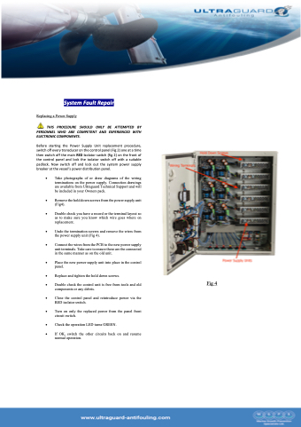
• Remove the hold down screws from the power supply unit (Fig4).
• Double check you have a record or the terminal layout so as to make sure you know which wire goes where on replacement.
• Undo the termination screws and remove the wires from the power supply unit (Fig 4).
• Connect the wires from the PCB to the new power supply unit terminals. Take care to ensure these are the connected in the same manner as on the old unit.
• Place the new power supply unit into place in the control panel.
• Replace and tighten the hold down screws.
• Double check the control unit is free from tools and old
components or any debris.
• Close the control panel and reintroduce power via the RED isolator switch.
• Turn on only the replaced power from the panel front circuit switch.
• Check the operation LED turns GREEN.
• If OK, switch the other circuits back on and resume normal operation.
Fig 4
