
Page 118 - eProceeding for IRSTC2017 and RESPeX2017
P. 118
Mohd Shah Rizan Nizam Abd Manap / JOJAPS – JOURNAL ONLINE JARINGAN COT POLIPD
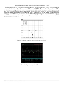
Simulation result return loss of the antenna is as shown in figure 3.2. Return loss is the loss of power in the signal reflected at
a line discontinuity. Based on the result, the resonance of the antenna is 1.96GHz. The range of the antenna is between 900 to
960 MHz. Based on the Figure 3.3 is the results of the frequency of the RFID antenna. The reader on the RFID system can only
detect the RFID tags between the ranges of the frequencies. Distance of the RFID antenna with the RFID tags are within 5
meters. The best reflected of the RFID tags should be done within a predetermined distance. By adjusting suitable distance and
avoidance of sources that interfere with the system such as cell phones, this system will operate successfully. Table 3.1 shows the
use of RFID cards in the convocation management system by percentage (%). These analyses are an improvement on using RFID
system from the previous problem.
Figure 3.2: Simulation of the return loss by using a spectrum analyser
Figure 3.3: Frequency range of the RFID antenna
116 | V O L 8 - I R S T C 2 0 1 7 & R E S P E X 2 0 1 7