
Page 459 - eProceeding for IRSTC2017 and RESPeX2017
P. 459
Mohamad Firdaus / JOURNAL ONLINE JARINGAN COT POLIPD
In aircraft structure design, one of the most important factors is load factor. Each design of aircraft has its own V-n diagram. Here
the V-n diagram is the same as RV-9 [8]. According to the V-n diagram below:
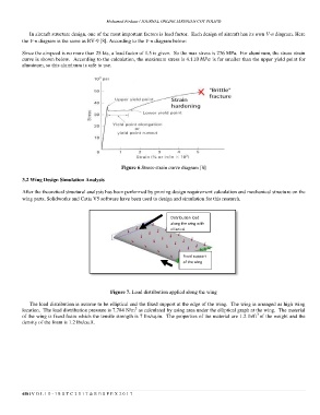
Since the airspeed is no more than 25 kts, a load factor of 1.5 is given. So the max stress is 276 MPa. For aluminum, the stress strain
curve is shown below. According to the calculation, the maximum stress is is far smaller than the upper yield point for
aluminum, so this aluminum is safe to use.
Figure 6.Stress-strain curve diagram [8]
3.2 Wing Design Simulation Analysis
After the theoretical structural analysis has been performed by proving design requirement calculation and mechanical structure on the
wing parts, Solidworks and Catia V5 software have been used to design and simulation for this research.
Distribution load
along the wing with
elliptical
Fixed support
of the wing
Figure 7. Load distribution applied along the wing
The load distribution is assume to be elliptical and the fixed support at the edge of the wing. The wing is arranged as high wing
2
location. The load distribution pressure is 7.784 N/m as calculated by using area under the elliptical graph at the wing. The material
3
of the wing is fixed foam which the tensile strength is 7 lbs/sq.in. The properties of the material are 1.2 lb/ft of the weight and the
density of the foam is 1.2 lbs/cu.ft.
458 | V O L 1 0 - I R S T C 2 0 1 7 & R E S P E X 2 0 1 7