
Page 581 - eProceeding for IRSTC2017 and RESPeX2017
P. 581
Eko Prasetyo / JOURNAL ONLINE JARINGAN COT POLIPD
Isomura et al (Isomura, et al., 2004) explained that gas turbine work under a closed Brayton cycle. Hence, it is important to
specify the target cycle, clarify and analyze the required performance of each component in the design stage. CFD is one of
simulation method tool used to analyzed or even optimize the MGT system performance. Han et al (Han, Seo, Park, Choi, & Do)
used 3D CFD to design a 500 W ultra-micro gas turbine generator. Meanwhile Lie et al (Li, Yin, Li, & Zhang, 2013) used CFD
to investigate the performance of the turbocharger centrifugal compressor when used as turbine in MGT.
The objective of this research is to analyze the flow in the turbocharger compressor when used as a micro gas turbine. Three
variations of compressor outlet diameter, combustion chamber and turbine performance were simulated using CFD software.
2. System Description
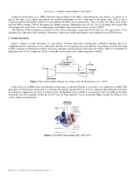
Figure 1 shows a simple schematic of a gas turbine. It shows that before entering the combustion chamber, the air is
compressed by the compressor. In the combustion chamber, the air temperature is increased by using energy from the fuel, such
as LPG. Leaving the combustion chamber, the high temperature working fluid is directed to the turbine, where it is expanded by
supplying power to the compressor and for rotating the electric generator or other equipment available.
Figure 1 Gas turbine system scheme of a simple cycle (do Nascimento, et al., 2013)
In this research, an RHF series (ball bearing) turbocharger, as shown in Figure 2, was used as the compressor of MGT. The
application of turbocharger compressor is to increase the pressure and the flow rate of the air that enter the combustion chamber.
In centrifugal compressors, air enters the blade axially. Furthermore, the air will flow in accordance with the profile of the blade
toward the rear of the impeller, so that the air will leave the blade radially. The air leaving the blades through the diffuser to the
volute, with increased pressure.
Figure 2 Unit RHF Turbocharger (IHI, 1999-2014)
577 | V O L 1 1 - I R S T C 2 0 1 7 & R E S P E X 2 0 1 7