
Page 23 - 2019종합카다로그_FLD
P. 23
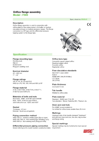
Orifice flange assembly
               Model : F500

                                                                           Spec. sheet no. FD05-01
               Description
               Orifice flange assembly is used in conjunction with
               orifice plate for flow measurement of smaller or medium
               size pipes at lower or medium pressure ranges. The flange
               connection is a RF type and the differential pressure
               tapping system is the flange taps.


               Specification

               Flange mounting type                     Orifice bore type
               Welding neck                             Concentric square edged orifice
               Slip-on                                  Quadrant edged orifice
               Socket-weld                              Eccentric orifice
               Ring-joint welding neck                  Segmental orifice

               Nominal diameter                         Flow claculation standards
               25 ~ 600 mm                              ISO 5167-1 and 2 2003
               1" ~ 24"                                 AGA-3
                                                        ASME MFC-3M (R.W Miller)
               Flange ratings                           L.K. Spink
                                                        JIS Z 8762
               JIS 10, 20, 30, 40 and 63 K
               ANSI (or JPI) 150, 300, 600 and 900 Lb RF
                                                        Plate thickness
               Flange material                          3,6,9 and 12 mm
               A105, A182-F304, A182-F316, A182-F11,    Tab handle
               A182-F22 and A350-LF2
                                                        Welded to orifice plate
               Materials of bolts and nuts              Plate material
               Stud blots : SNB7, A193-B7 and A194-B8   Standard : 304SS and 316L SS
               Nuts : S45C, A194-2H and A194-8          Non-standard : Monel, Hastelloy B/C, Titanium etc.
               Jack bolts and nuts : S25C and A307
                                                        Drain and vent hole
               Gasket                                   Per ASME recommendations
               Thickness : 4.5 mm                       Not drilled for orifice bores smaller than 25.4 mm
               Material : Spiral wound gaskets
                                                        Markings
               Piping connection method                 Upstream side of tab handle stamped "Upstream"
               ANSI 150 Lb : Insertion welding type (Slip-on type)  and with bore type and size, line size, tag number
               ANSI 300, 600 Lb : Butt welding type (Welding neck)  and flange rating
               ANSI 900 Lb : Butt welding neck (Ring-joint WN)
                                                        Special markings
               Differential pressure piping connection  Special marking may be furnished to meet special
               Select referring to the model number construction table  requirement


                                                                                                F500_01