
Page 29 - DelcoSalesPlayBook2020!
P. 29
Pipe Hangers
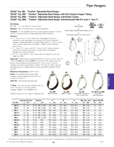
TOLCO Fig. 200 - “Trimline” Adjustable Band Hanger
™
™
TOLCO Fig. 200F - “Trimline” Adjustable Band Hanger with Felt Lining for Copper Tubing
™
TOLCO Fig. 200C - “Trimline” Adjustable Band Hanger with Plastic Coated
™
TOLCO Fig. 200S - “Trimline” Adjustable Band Hanger with Removable Nut (For sizes 1” thru 2”)
† †
Size Range: A
1
Fig. 200 - /2” (15mm) thru 8” (200mm) pipe Overall Height
Material: Steel, Pre-Galvanized to G90 specifications B
Center of pipe to top of knurled hanger rod nut.
Function: For fire sprinkler and other general piping purposes. Knurled
D
swivel nut design permits hanger adjustment after installation.
Top of pipe to bottom of hanger rod nut.
Features:
Fig.
• 1 /2” (15mm) thru 2” (50mm) sizes have flared edges for ease of 200- /2 &
1
installation on all pipe types and protects CPVC plastic pipe from 3
200- /4
abrasion. Captured knurled nut design (flared top) on 1” thru 2” sizes D
keep nut from separating with hanger. Hanger is easily installed
around pipe.
3
1
• 1 /2” (15mm), /4” (20mm), and 2 /2” (65mm) thru 8” (200mm)) Spring B
tension on nut holds it securely in hanger before installation.
Knurled nut is easily removed. A
3
1
• For /2” (15mm) and /4” (20mm) sizes with non-captured knurl nuts
order Fig. 200S
Fig.
1
Approvals: Underwriters Laboratories listed ( /2” (15mm) thru 8” (200mm)) 1
in the USA (UL) and Canada (cUL) for steel and CPVC plastic pipe and Fig. 200-2 /2 to 200-8
3
Factory Mutual Engineering Approved ( /4” (20mm) thru 8” (200mm)). 200-1 to
Conforms to Federal Specifications WW-H-171E & A-A-1192A, Type 10 200-2
and Manufacturers Standardization Society ANSI/MSS SP-69 & SP-58,
Type 10.
Maximum Temperature: 650°F (343°C)
Finish: Pre-Galvanized. Stainless Steel
materials will be supplied with (2) hex nuts
Pipe Hangers
in place of a knurl nut.
Order By: Part number and pipe size
** Note: For metric hanger rod sizes add the
metric rod size to the figure number.
1
1
Example: 200M8-1 /2 or 200M10-1 /2
Fig. 200C Fig. 200F Fig. 200 Fig. 200 & Fig. 200S
1
1
† M8 rod size is not UL Listed or FM Approved 200C-1 /2 shown 200F-1 /2 shown shown with captured nut shown with
1” thru 2” sizes only non-captured nut
Nominal Pipe Size Rod Size A B D Max. Rec. Load Approx. Wt./100
Part No.** in. (mm) in. mm** in. (mm) in. (mm) in. (mm) lbs. (kN) lbs. (kg)
1 1 3 1 5 11
200- /2 /2" (15) /8"-16 M8† or M10 3 /8" (79.4) 2 /8" (66.7) 1 /32" (34.1) 400 (1.78) 11 (5.0)
3 3 3 1 1 1
200- /4 /4" (20) /8"-16 M8† or M10 3 /8" (79.4) 2 /2" (63.5) 1 /16" (27.0) 400 (1.78) 11 (5.0)
3
5
1
200-1 1" (25) 3 /8"-16 M8† or M10 3 /8" (85.7) 2 /8" (66.7) 1 /8" (28.6) 400 (1.78) 12 (5.5)
1 1 3 3 7 5
200-1 /4 1 /4" (32) /8"-16 M8† or M10 3 /4" (94.0) 2 /8" (73.0) 1 /32" (29.3) 400 (1.78) 13 (5.9)
1 1 3 7 7 3
200-1 /2 1 /2" (40) /8"-16 M8† or M10 3 /8" (98.4) 2 /8" (73.0) 1 /16" (30.2) 400 (1.78) 14 (6.4)
3
1
200-2 2" (50) 3 /8"-16 M8† or M10 4 /2" (114.3) 3" (76.3) 1 /16" (30.2) 400 (1.78) 15 (6.9)
1 1 3 5 1 7
200-2 /2 2 /2" (65) /8"-16 M10 5 /8" (142.9) 4 /8" (104.7) 1 /16" (36.5) 600 (2.67) 27 (12.3)
7
1
200-3 3" (75) 3 /8"-16 M10 5 /8" (149.1) 4" (101.6) 1 /4" (31.7) 600 (2.67) 29 (13.3)
1 1 3 3 1 3
200-3 /2 3 /2" (90) /8"-16 M10 7 /8" (187.3) 5 /4" (133.3) 2 /16" (55.6) 600 (2.67) 34 (15.6)
3
3
200-4 4" (100) 3 /8"-16 M10 7 /8" (187.3) 5" (127.0) 1 /8" (34.9) 1000 (4.45) 35 (16.0)
1
1
11
200-5 5" (125) 1 /2"-13 M12 9 /8" (231.8) 6 /4" (158.7) 3 /32" (84.9) 1250 (5.56) 66 (30.2)
7
3
1
200-6 6" (150) 1 /2"-13 M12 10 /8" (257.2) 6 /4" (171.4) 2 /32" (56.3) 1250 (5.56) 73 (33.4)
1
7
3
200-8 8" (200) 1 /2"-13 M12 13 /8" (333.4) 8 /4" (222.2) 3 /32" (81.7) 1250 (5.56) 136 (62.3)
All dimensions in charts and on drawings are in inches. Dimensions shown in parentheses are in millimeters unless otherwise specified.
B-Line series Pipe Hangers & Supports Eaton
61