
Page 2257 - Workshop Manual - Tunland (2017)
P. 2257
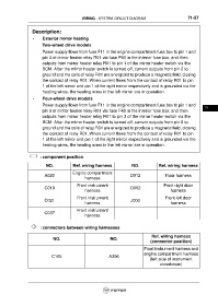
WIRING - SYSTEM CIRCUIT DIAGRAM                             71-57


                   Description:

                   •     Exterior mirror heating
                         Two-wheel drive models

                         Power supply flows from fuse F11 in the engine compartment fuse box to pin 1 and
                         pin 3 of mirror heater relay R01 via fuse F40 in the interior fuse box; and then
                         outputs from mirror heater relay R01 to pin 1 of the mirror heater switch via the
                         BCM. After the mirror heater switch is turned off, current outputs from pin 2 to
                         ground and the coils of relay R01 are energized to produce a magnetic field, closing
                         the contact of relay R01. When current flows from the contact of relay R01 to pin
                         1 of the left mirror and pin 1 of the right mirror respectively and is grounded via the
                         heating wires, the heating wires in the left mirror are in operation.
                   •     Four-wheel drive models
                         Power supply flows from fuse F11 in the engine compartment fuse box to pin 1 and
                                                                                                                     71
                         pin 3 of mirror heater relay R01 via fuse F40 in the interior fuse box; and then
                         outputs from mirror heater relay R01 to pin 3 of the mirror heater switch via the
                         BCM. After the mirror heater switch is turned off, current outputs from pin 8 to
                         ground and the coils of relay R01 are energized to produce a magnetic field, closing
                         the contact of relay R01. When current flows from the contact of relay R01 to pin
                         1 of the left mirror and pin 1 of the right mirror respectively and is grounded via the
                         heating wires, the heating wires in the left mirror are in operation.


                        : component position


                           NO.            Ref. wiring harness              NO.            Ref. wiring harness
                                          Engine compartment
                          A020                                            D012                Floor harness
                                                 harness
                                            Front instrument                                 Front right door
                          C019                                            G002
                                                 harness                                         harness

                                            Front instrument                                  Front left door
                          C021                                             J003
                                                 harness                                         harness
                                            Front instrument
                          C037
                                                 harness


                        : connectors between wiring harnesses

                                                                                      Ref. wiring harness
                               NO.                             NO.
                                                                                      (connector position)

                                                                                  Front instrument harness and
                                                                                  engine compartment harness
                              C105                            A306
                                                                                     (left side of instrument
                                                                                           crossbeam)