
Page 80 - Eric C. Fry - Knots and Ropework
P. 80
47 The regulations governing the use of wire eye splices in industry
are necessarily strict and whilst the following eye splices,
Admiralty Admiralty and Uverpool (Knot 48) are considered to be adequate
for normal usage, the reader, if considering either splice from the
point of view of insurance and/or the regulations must refer back
Eye Splice to the regulations, in force at the time.
The main feature of the Admiralty eye splice is, that after the first
tuck, all strands are tucked away Oller one/under one, against the
fay of the standing part.
There are also, Slleas! three methods of completing the first fu ll
tuck, the one illustrated being the 1-6-2-3-5-4 order of tucking.
The required size of the eye is established and a seizing put on
accordingly, after which all strands are unlaid, ensuring that they
are in their right order, the heart being always associated with the
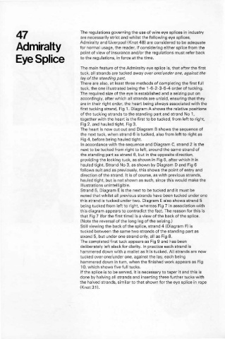
first tucking strand, Fig 1. Diagram A shows the relative positions
of the tucking strands to the standing part and strand No 1,
together with the heart is the first to be tucked, from left to right,
Fig 2, and hauled tight, Fig 3.
The heart is now cut out and Diagram B shows the seQuence of
the next tuck, when strand 6 is tucked, also from left to right as
Fig 4, before being hauled tight.
In accordance with the seQuence and Diagram C, strand 2 is the
next to be tucked from right to left, around the same strand of
the standing part as strand 6, but in the opposite direction.
providing the locking tuck. as shown in Fig 5. after which it is
hauled tight. Strand No 3. as shown by Diagram D and Fig 6
follows suit and as previously. this shows the point of entry and
direction of the strand. It is of course, as with previous strands,
hauled tight, but is not shown as such, since this would make the
illustrations unintelligible.
Strand 5. Diagram E is the next to be tucked and it must be
noted that whilst all previous strands have been tucked under one
this strand is tucked under two. Diagram E also shows strand 5
being tucked from left to right. whereas Fig 7 in association w ith
this diagram appears to contradict the fact. The reason for this is
that Fig 7 (for the first time) is a view of the back of the splice.
(Note the reversal of the long leg of the seiling.)
Still viewing the back of the splice, strand 4 (Diagram F) is
lUcked between the same two strands of the standing part as
strand 5, but under one strand only, all as Fig 8.
The completed first tuck appears as Fig 9 and has been
deliberately left slack for clarity. In practice each strand is
hammered down with a mallet as it is lUcked. All strands are now
tucked over one/under one, against the lay, each being
hammered down in turn, when the finished work appears as Fig
10, which shows five full tucks.
If the splice is to be served. it is necessary to taper it and this is
done by halving all strands and inserting three further tucks with
the halved strands, similar to that shown for the eye splice in rope
(Knot 31).