
Page 97 - ISU Echague LUDIP
P. 97
DESIGN CONSIDERATIONS
Retrofit Roof Fastening
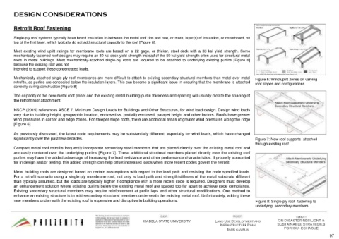
Single-ply roof systems typically have board insulation in-between the metal roof ribs and one, or more, layer(s) of insulation, or coverboard, on
top of the first layer, which typically do not add structural capacity to the roof [Figure 8].
Most existing wind uplift ratings for membrane roofs are based on a 22 gage, or thicker, steel deck with a 33 ksi yield strength. Some
mechanically-fastened roof designs may require an 80 ksi deck yield strength instead of the 50 ksi yield strength often used for structural metal
roofs in metal buildings. Most mechanically-attached single-ply roofs are required to be attached to underlying existing purlins [Figure 8]
because the existing roof was not
intended to support these concentrated loads.
Mechanically-attached single-ply roof membranes are more difficult to attach to existing secondary structural members than metal over metal Figure 6: Wind uplift zones on varying
retrofits, as purlins are concealed below the insulation layers. This can become a significant issue in ensuring that the membrane is attached roof slopes and configurations
correctly during construction [Figure 8]
The capacity of the new metal roof panel and the existing metal building purlin thickness and spacing will usually dictate the spacing of
the retrofit roof attachment.
NSCP (2015) references ASCE 7, Minimum Design Loads for Buildings and Other Structures, for wind load design. Design wind loads
vary due to building height, geographic location, enclosed vs. partially enclosed, parapet height and other factors. Roofs have greater
wind pressures in corner and edge zones. For steeper slope roofs, there are additional areas of greater wind pressures along the ridge
[Figure 6].
As previously discussed, the latest code requirements may be substantially different, especially for wind loads, which have changed
significantly over the past few decades. Figure 7: New roof supports attached
through existing roof
Compact metal roof retrofits frequently incorporate secondary steel members that are placed directly over the existing metal roof and
are easily centered over the underlying purlins [Figure 7]. These additional structural members placed directly over the existing roof
purlins may have the added advantage of increasing the load resistance and other performance characteristics. If properly accounted
for in design and/or testing, this added strength can help offset increased loads when more recent codes govern the retrofit.
Metal building roofs are designed based on certain assumptions with regard to the load path and resisting the code specified loads.
For a retrofit scenario using a single-ply membrane roof, not only is load path and strength/stiffness of the metal substrate different
than typically assumed, but the loads are typically higher if compliance with a more recent code is required. Designers must develop
an enhancement solution where existing purlins below the existing metal roof are spaced too far apart to achieve code compliance.
Existing secondary structural members may require reinforcement at purlin laps and other structural modifications. One method to
enhance an existing structure is to add secondary structural members underneath the existing metal roof. Unfortunately, adding these
new members underneath the existing roof is expensive and disruptive to building operations. Figure 8: Single-ply roof fastening to
underlying secondary members
CONTENT:
ISABELA STATE UNIVERSITY Land Use Development and ON DISASTER-RESILIENT &
Infrastructure Plan SUSTAINABLE STRATEGIES
FOR ISU - ECHAGUE
Main campus
97