
Page 53 - kursus eBook
P. 53
DRAFT GUIDELINE ON DOMESTIC GAS PIPING SYSTEM
conditions (Zone 1) or in abnormal conditions (Zone 2). A storage container and other
specified gas equipment and handling facilities such as relief valve discharge, vaporisers
and filling points shall be located so that a fixed ignition source does not fall within a
hazardous area classified as zone 0, 1 or 2 surrounding the above points.
Only intrinsically safe electrical equipment (equipment that cannot cause ignition when in
contact with flammable or explosive atmospheres) can be used in Zone 0, whilst
flameproof/explosion-proof electrical equipment (equipment which contains the explosion
within a housing, preventing the ignition of the surrounding atmosphere) may be used in
Zone 2 or 3.
An effective earthing point and/or bonding connection shall be provided at the storage site
for discharging static electricity from bulk tank vehicles prior to commencing the delivery
operation. In addition, storage containers greater than 2.5 kl water capacity shall be
electrically earthed as a protection against the accumulation of static electricity.
The placing of storage containers within 1.5 m measured horizontally from the vertical plane
of overhead transmission lines shall be avoided.
Manifolded cylinders location
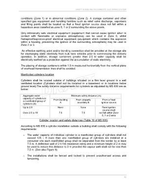
Cylinders shall be located outside of buildings situated on a firm level ground in a well
ventilated location (Cylinders shall not be installed in a basement or in locations below
ground level).The safety distance requirements for cylinders as stipulated by MS 830 are as
below:
Aggregate water Minimum safety distance (m)
capacity of cylinders in From building From property From a fixed
a manifolded group of
cylinders (kl) A boundary B ignition source
Up to 2.5 None None Fixed ignition
source shall
Over 2.5 to 10 7.5 7.5 not fall within Zone
0, 1 or 2 area
Cylinder location and safety distances (Table 10 of MS 830)
According to MS 830 a cylinder installation outside a building shall comply with the following
requirements:
o The water capacity of individual cylinder in a manifolded group of cylinders shall not
exceed 125 l. If more than one manifolded group of cylinders are installed at a
consumer site each manifolded group shall be separated from the border by at least
7.5 m. A deflection wall of 2 h fire resistance rating and a minimum height of 2 m may
be used to reduce this distance to 3 m provided the vapour path shall not be less than
7.5 m. (See also Figure 9)
o The installations shall be fenced and locked to prevent unauthorised access and
tampering.
13