
Page 23 - 100 Claremont Complete
P. 23
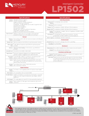
LP1502
part of HID Global Intelligent Controller
Specifications Specifications
Access 240,000 cardholder capacity Cable Requirements
Control 50,000 transaction buffer
Supports total of 1 RS-485 IO protocols Power and 1 twisted pair, 18 to 16 AWG
255 access levels per cardholder Relays
Cardholder - 19 Digit (64 Bit) User ID with 15 digit PIN MAX Ethernet CAT-5, minimum
Activation/Deactivation
If/Then macro capabilities Reader TTL 6-conductor, 18 AWG, 500 feet (150 m) maximum
Anti-passback support
Nested, area, hard, soft and timed forgiveness Reader F/2F 4-conductor, 18 AWG, 500 feet (150 m) maximum
Adjustable cardholder capacity
Supports up to 520 inputs and 516 outputs Reader 1 twisted pair, shielded, 120 ohm impedance, 24 AWG, 2,000
RS-485 ft. (610 m) max.
Door Control Natively supports for up to 4 readers and 2 openings.
Expands to support up to 64 readers and openings I/O Devices 1 twisted pair with drain wire and shield, 120 ohm
impedance, 24 AWG, 4,000 ft. (1,219 m) maximum
General
Alarm Input 1 twisted pair, 30 ohms maximum
Primary 12 to 24 Vdc ± 10 %, 500 mA maximum (reader and USB ports
Power not included) Environmental
Reader Port 600 mA maximum (add 600 mA to primary power current) Temperature -55 to +85 °C, storage, 0 to +70 °C, operating
Humidity 5 to 95% RHNC
Micro USB 5 Vdc, 500 mA maximum (add 270 mA to primary power
Port current) Mechanical
Battery Memory/ Clock Backup: 3 Volt Lithium, type BR2330 or Dimensions 8 in. (203.2 mm) W x 6 in. (152.4 mm) L x 1 in. (25 mm) H
CR2330
Weight 9 oz. (255 g) nominal, board only
microSD Card microSD or microSDHC; 2GB to 8GB
Compliance and Warranty
Host Comm. Ethernet: 10-BaseT/100Base-TX and USB port (2.0) with Product UL294 Recognized, FCC Part 15 Class A, CE Compliant, RoHS,
optional adapter: pluggable model USB2-OTGE100 Compliance NIST Certified Encryption
Serial I/O 2-wire RS-485, 2,400 to 115,200 bps, asynchronous, half- Warranty Mercury Security warrants the product is free from defects
Device duplex, 1 start bit, 8 data bits, and 1 stop bit in material and workmanship under normal use and service
Inputs Eight unsupervised/supervised, standard EOL: 1k/1k ohm, with proper maintenance for one year from the date of
1%, ¼ watt. Two unsupervised dedicated for cabinet tamper factory shipment.
and UPS fault monitoring
Output Four relays, Form C, NO 5 A @ 30 Vdc resistive,
Relays NC 3 A @ 30 Vdc resistive
Reader Interface
Reader 12-24 Vdc ± 10 % regulated, 300 mA maximum each reader
Power
Data Inputs TTL compatible, F/2F or 2-wire RS-485
RS-485 Mode 9,600 to 115,200 bps, asynchronous, half-duplex, 1 start bit,
8 data bits, and 1 stop bit. Maximum cable length: 2000 ft.
(609.6 m)
LED Output TTL levels, high>3 V, low<0.5 V, 5 mA source/sink maximum
Buzzer Open collector, 12 Vdc open circuit maximum, 40 mA sink
Output maximum
Network Switch
To Mercury OEM Host
1 1 1 1 1
TB1 TB2 TB3 VIN J5 POE TB5 TB6
1 VO GND VIN GND
TB4 K1
CAT5/CAT 6 TB7 K2 K3 K4 K1 K2 K3 K4
1
J3 J4
4 3 2 1 J1
ON S1 | | V 10519-0000-F, REV-A
3
7 6 5 4 2 1
3V BR/CR2330
1 RESET VIN
2 GND MR62e Door 2
3 TMP Door 1
4 S2 GND
5 BT1 FLT
R1 GND
R2 TB1 J2
1 S1 D16
3 2
ON V | | | | | | 4 GND_C
TB8 RS-485
GND J6
VIN
DAT D0
CLK READER 1 D1
LED J5 J8
Door 1 READER 2 TB9 GND DAT CLK D0 VO VIN TR+ TB3 TR- GND TB4 IN1 READER 1 DAT D1 GND D0 VO TB8 LED TB9 D1 READER 2 D0 MR52+ RLY 1 NC NO CNCTB10 RLY 2 RLY 3 RLY 4 TB12 C NC TB11 RLY 5 RLY 6 TB1 I1 I1 I2 1 2 9 10 TB5 TB5 I9 I9 I10 OUT 1 NO C NC TB1 1 2 3 4 5 6 7 8 9 10 11 12 13 14 15 16 TB5 NC C NO OUT 9
LED D1 IN2 VO LED BZR CLK BZR CLK GND DAT 1 4 3 2 1 5 4 3 2 8 7 6 C NO C NC NO NC NO C NO NC NO C TB2 I2 3 4 11 12 I10 TB6 NO C K1 K9 NC C
VO I3 5 13 I11 NC NO OUT 10
NO PASS 12V S2 S1 K1 I3 14 I11 OUT 2 TB2 K2 TB6
OUT 1 C J7 IN3 ^ | TB4 TB3 NC I4 6 7 15 I12 NO C K10 NC C
NC IN4 ON GND I4 8 16 I12 NC NO
NO TB5 I5 TB3 CT I13 TB7 OUT 3 K3 K11 OUT 11
OUT 2 C TB6 K1 K2 K3 K4 K5 K6 C I5 I13 OUT 4 NO NC OUT 12
NC TB10 IN5 PFLR1R2 12VPT BZR D4 D3 NO K1 I6 BA I14 C NC K4 S1 1 2345678 S2 1234 K12 C NO
NO IN6 J1 LED I6 I14 TB3 TB7
OUT 3 C TB11 K 8 TMP NO TB4 I7 TB8 I15 NO NC
NC 1 TB7 CLK K2 C K5 K13 C
OUT 4 NO C 2 K K 3 IN7 7 6 D1 DAT I7 I8 I15 I16 OUT 5 NC NO OUT 13
NC K 4 IN8 5 D0 NC K2 C TB9 I8 I16 NO C K6 K14 NC C
4 VO CT NC NO OUT 14
3 VIN GND S2 1 OUT 6 TB4 K7 K15 TB8
2 TR+ BA GND 3 2 4 NO C NC C
1 B TR- GND S1 2 1 OUT 7 NC K8 K16 NO OUT 115
LP15
LP1502
LP15
LP15 02 A GND TB1 J2 I2 I2 3 5 4 6 NO C NC NC C NO OUT 16
LP15
02
02
L LP
LP1502
02
J4
ON--> 8 7 OUT 8 TB9
TB6 TB7 J1 ^ | I1 CT A B
TB1 IN1 IN2 IN3 TB2 IN4 IN5 TB3 IN6 TB4 IN7 IN8 TMP TB5 GND PFL GND TR+ TR- NC NC GND VIN VOUT GND S1 I1 TB10 GND CT
INPUTS RS-485 TB2 TR+ TR- J3 A B BA GND BA
1 2 3 4 5 6 7 8 ON D2 D1 RS-485 K1 K2 TB10 TR+
MR52 GND TB11 K1 TB12 NC OUT 1 RS-485 TR- J1
Door 2 MR50 VIN VOUT GND K2 C NO NC OUT 2 C GND VIN TB11 VOUT
Door 1 NO GND
MR16IN MR16OUT
The Authentic Mercury open platform delivers quality assurance derived from the most proven and reliable hardware in the
industry. Driven by our engineering excellence and technology leadership, Authentic Mercury hardware is designed as an access
control platform that easily encompasses emerging technologies, changing industry standards and evolving system environments.
Make yours Authentic, Make sure its Merc.
LP1502 July 2018