
Page 141 - Basic Monitoring in Canine and Feline Emergency Patients
P. 141
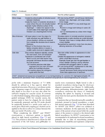
Table 7.1.  Continued.

  VetBooks.ir  Artifact    Causes of artifact               How the artifact appears
              Mirror image
                                                            DH view during AFAST , air-soft tissue interference
                                                                            3
                           Created by altered paths of reflected sound
                            between interfaces
                           Create the illusion of anatomic structures in   between liver, diaphragm, and lungs creates
                                                              mirror image
                                                                            3
                            areas where they are not actually located  SR view during AFAST  in very small dogs and
                           Example: highly reflective surface of the   cats:
                            diaphragm → makes liver appear to be   Possible to image both kidneys in same US
                            on both sides of the diaphragm (could be   image
                            mistaken as a diaphragmatic hernia)  Can be misinterpreted as a false mirror image
                                                                artifact
              Slice thickness  US beam plane is near the edge of a   Simulates debris in normally anechoic structures
                            cystic structure (e.g. gall bladder or   Misrepresents a cystic structure as a solid structure
                            urinary bladder), echoes are received   Example: false mass or sludge effects within the
                            from outside the structure due to beam's   urinary bladder
                            thickness.                      Recognized by scanning in more than one plane,
                           ‘Filling-in’ of the structure may occur →   allowing resolution of the artifact
                            falsely simulates debris or causes a
                            smaller cystic structure to appear solid
              Side lobe    Stray echoes displaced laterally, outside   Side lobe artifact similar in appearance to slice
                            the main beam, from US transducer  thickness
                           Transducer is positioned over a fluid-  Creates the appearance of echogenic material
                            filled structure and ‘side beams’ may   within a fluid-filled structure:
                            encounter soft tissue structure outside   Example: bowel gas near the gall bladder or
                            the fluid structure:              urinary bladder creating a strong reflection
                             US machine assumes side lobes    confused with echogenic debris or calculi
                               originated from the main US beam   DH view during AFAST  predisposed to side lobe
                                                                            3
                               within the fluid-filled structure  and edge shadowing artifacts:
                             US machine places the echogenic   Causes decreased clarity along luminal borders
                               signal within the fluid        Gives false appearance of sediment
              AFAST , abdominal focal assessment sonographically for trauma/triage/tracking; CC, cystocolic; DH, diaphragmaticohepatic; HR,
                  3
              hepatorenal; SR, splenorenal; TFAST , thoracic focal assessment sonographically for trauma/triage/tracking; US, ultrasound.
                                     3
             probe with a minimum frequency of 7.5  MHz   nearly every examination. Right lateral is also a
             should be utilized as it has superior detail for   standard recumbency during triage for electrocar-
             superficial structures. However, a curvilinear probe   diogram assessment (see Chapter 3). Additionally,
             with a frequency range of 5–8 MHz with an adjust-  when performing abdominocentesis, right lateral
             able depth to less than 4  cm may also allow for   recumbency minimizes the chance of mistakenly
             sufficient imaging for vascular access. In contrast   sampling the spleen by keeping it elevated and
             to other bedside imaging, when using an ultrasound-   away from the more gravity-dependent free abdom-
             guided technique (UST) for vascular access, the   inal fluid.
             patient needs to have fur clipped, the site should   In patients that are hemodynamically unstable or
             be aseptically prepared, and the US probe should   extremely stressed in lateral recumbency  a modi-
             be aseptically housed in a sterile cover such as a   fied sternal approach (Fig. 7.4) has been described
                                                                  3
                                                                             3
             sterile glove filled with coupling gel. Alcohol can be   for AFAST   and TFAST  (albeit not validated in
             applied to the skin to allow for contact between the   veterinary medicine). In this approach, the cranial
             skin and sterile US probe cover.            aspect of the patient is kept sternal while the caudal
               When completing the  AFAST   and TFAST    aspect of the patient is rotated to the desired right
                                        3
                                                    3
                                                                                 3
             examinations, a veterinary patient is typically   lateral recumbency. An AFAST  examination is not
             placed in right lateral recumbency (Figs 7.2 and   recommended to be performed in dorsal recumbency,
             7.3). This position is ideal because it allows for full   primarily due to risks of exacerbating potential
             assessment of the left kidney and gallbladder in   hemodynamic instability and respiratory compromise
             Applications of Serial Focal Ultrasound Techniques in the Hospitalized Small Animal Patient   133