
Page 1624 - Flipbook_SolidDesignSoutheast2020
P. 1624
F lexible Containment Solution S Gui D e
Offloading with a continuous liner system
Utilizing a similar multiple o-ring groove canis-
®
ter, ArmorFlex film, and crimping technique
as above, this system allows contained of- 1
floading into drums. Liners are factory packed
with standard bundles of 150’ (45 m), 100’ (30
m), and 50’ (15 m). Custom lengths are also
provided.
Gemco V-Blender to Continuous Liners
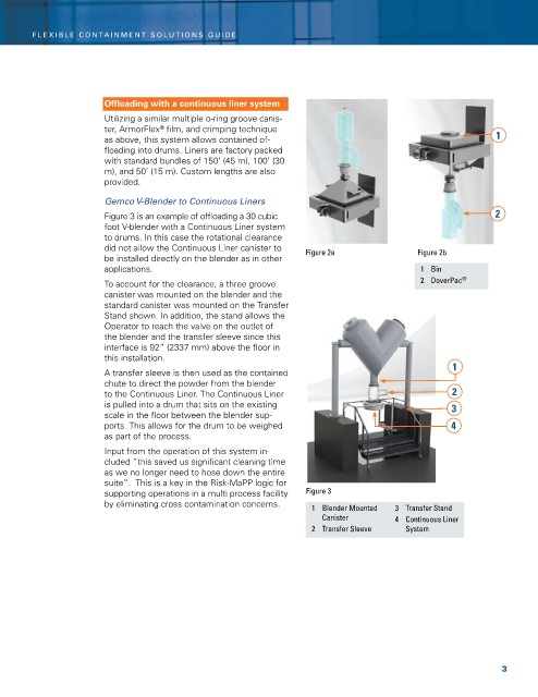
Figure 3 is an example of offloading a 30 cubic 2
foot v-blender with a Continuous Liner system
to drums. in this case the rotational clearance
did not allow the Continuous Liner canister to Figure 2a Figure 2b
be installed directly on the blender as in other
applications. 1 Bin
To account for the clearance, a three groove 2 DoverPac ®
canister was mounted on the blender and the
standard canister was mounted on the Transfer
Stand shown. in addition, the stand allows the
Operator to reach the valve on the outlet of
the blender and the transfer sleeve since this
interface is 92” (2337 mm) above the floor in
this installation.
1
A transfer sleeve is then used as the contained
chute to direct the powder from the blender
to the Continuous Liner. The Continuous Liner 2
is pulled into a drum that sits on the existing 3
scale in the floor between the blender sup-
ports. This allows for the drum to be weighed 4
as part of the process.
input from the operation of this system in-
cluded “this saved us significant cleaning time
as we no longer need to hose down the entire
suite”. This is a key in the risk-MaPP logic for
supporting operations in a multi process facility Figure 3
by eliminating cross contamination concerns. 1 Blender Mounted 3 Transfer Stand
Canister 4 Continuous Liner
2 Transfer Sleeve System
3