
Page 1766 - Flipbook_SolidDesignSoutheast2020
P. 1766
®
Coaxial DoverPac - Nanogram Powder Transfer
Containment
Systems
OVER VIEW
The Coaxial neck DoverPac was originally designed to allow secondary containment to be used
®
with a DoverPac in the late 1990’s for charging and offloading vessels through isolators. Given
®
the increase in highly potent API manufacturing, the use of this system with either rigid isolators
or flexible enclosures is a complimentary processing option.
The Coaxial Neck DoverPac serves the dual function of contained transfer and storage system.
®
These are available in standard 45, 185, 400, and 700Liter volumes. Custom sizes can also be
accommodated.
1. Vessel Outlet
HOW DOES IT WORK?
2. Flexible Enclosure
This system is designed to provide containment 3. Inner Neck
to the OEB 5 (less than 1 μg/m3 with a goal of Attachment
below 200 nanograms/m3 on a task basis). To 1 4. Support Frame
achieve this, the secondary containment (i.e. 5. Outer Neck
flexible enclosure and the outer neck) at the 3 2 Attachment
primary connection points are applied. Figure
1 shows the offloading set up during exposure
monitoring trials.
The installation sequence follows:
• The top of the enclosure is attached to the
first canister on the vessel outlet. 4
• The bottom of the enclosure is attached to 5
the canister on the support frame.
• The external neck on the DoverPac is then
®
attached to the outlet point of the canister
on the frame.
• The internal neck of the DoverPac is pulled up
®
through the lower canister and is attached to
the groove on the vessel canister by using the
integral glove sleeves on the flexible enclosure. Figure 1
Once the vessel is offloaded, the internal neck is crimped off and pushed back down through the
canister on the frame by using the enclosure to access the neck area. The operator then extracts
his/her arms from the enclosure and crimps off the external neck.
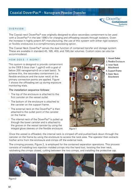
The crimping process, Figure 2, is employed for the contained separation operations. This process
consists of installing two injection molded crimps into the hand tool, twisting the liner neck,
ratcheting the crimps closed, cutting between the two crimps, and installing the protective cap.
Figure 2
32