
Page 1794 - Flipbook_SolidDesignSoutheast2020
P. 1794
Mill Containment System
Containment
Systems
OVER VIEW
Milling is a common operation throughout the Pharmaceutical Manufacturing Process. Sizing of
powders is a dusty operation and with more potent powders being processed the need for containing
this operation becomes even more critical from safety and cross contamination avoidance purposes.
In addition to contained powder throughput, it is imperative that access to the interior of the
mill be made available without breaking containment in case the screen blinds, for changing
to a different mesh, impeller change, or cleaning.
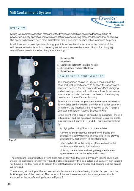
1. Underdrive Mill
2. DoverPac ®
2 3. Charging Canister with Transition Adapter
4. Screen Access Enclosure Hardware
5. Outlet Canister
HOW DOES THE SYSTEM WORK?
3 The configuration shown in Figure 1 consists of the
basic mill with modifications to support the attachment
hardware needed for the standard DoverPac ® charging
and offloading systems. In addition, a flexible enclosure
4 interface is provided between the base of the charging
canister and the mill’s inlet housing.
Safety is maintained as provided in the base mill design.
1 Safety Grids are included in the inlet and outlet canisters.
5 In addition, the interlocks are relocated to the Charging
Canister and Screen Access Enclosure Ring.
In the event that a screen blinds during operation, the mill
is turned off and the screen is accessed using the enclo-
sure shown in Figures 2, 3, and 4. This is accomplished
by:
• Applying the Lifting Shroud to the canister
• Removing the protective shroud from around the
enclosure (used when the enclosure is in the stowed
position only, not shown in this document)
Figure 1
• Inserting hands in the integral glove sleeves in the
enclosure and opening the tri-clamp
• Hoisting the canister and using the glove sleeves
again to remove the impeller and screen
The enclosure is manufactured from clear ArmorFlex film that will allow room light to illuminate
®
inside the enclosure for easy viewing. It is also equipped with a bag in/bag out sleeve which is used
for housing the tool needed to loosen the bolt that secures the impeller and bagging out the screen
as required.
The opening at the top of the enclosure includes an encapsulated o-ring that is clamped onto the
bottom groove of the canister. The bottom of the enclosure has a similar arrangement that is
clamped to the interface ring shown in Figure 3.
60