
Page 2861 - Flipbook_SolidDesignSoutheast2020
P. 2861
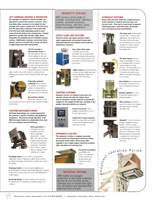
MARKETS SERVED
        LIFT CARRIAGE DESIGNS & OPERATION    NBE serves a wide range of          HYDRAULIC SYSTEMS
        Lift carriages are offered in several available con-  markets including food, chemical,   Power units and valve stacks are configured based
        figurations to match the customer’s process.  Floor   plastics, personal products,   on the customer’s required cycles per hour and
        load styles allow containers to be loaded into the   pharmaceutical, pet food, dairy,   time per cycle.  They can be constructed for general
        carriage with casters, a pallet jack, or fork lift truck.    rubber and water treatment.  industrial purpose, wash down duty, intrinsically
        Fork lift styles allow containers to be loaded with                      safe, and explosion proof classifications.
        a fork lift truck while eliminating metal to metal
        contact from the forks to the carriage base.  Integral                                 The power unit includes a large
        powered or gravity roller conveyor styles allow   SAFETY CAGE AND SYSTEMS              reservoir with a return line filter,
        integration into indexing and accumulation conveyor   Standard safety cage option includes 2-sided   sight gauge, and vented fill cap.
        systems.  Additionally, conveyors can include chain   safety caging panels constructed of sheet steel   The power units are mounted
        transfer devices to transfer full or empty conveyors   with polycarbonate view windows and cut-outs for   to the framework or can be skid
        at right angles from their load position.  maintenance purposes.                       mounted to include a drip-pan
                                                                                               that helps prevent fluid from
                       The lift carriage is               Four sided safety cages              reaching the floor.
                       hydraulically raised into          completely surrounds the
                       the discharge hood with cam        discharger and has hinged doors
                       rollers traveling on track bars    that are electrically interlocked with
                       to guide the lift and provide the   the controls to stop or prevent the   The valve stacks provide a
                       smoothest operation possible       discharger’s operation if the doors   range of adjustability to control
                       while eliminating the potential    are opened.                          the discharger’s lift and rotation
                       for side to side racking found in                                       speed, as well as the seal
                       other designs.  A timing circuit                                        pressure.  The seal pressure can
                       along with a pressure reducing      Light curtains eliminate the need   be adjusted for different styles
        valve is used to ensure the container is sealed without   to open and shut safety cage doors   of containers to provide a very
        damaging the container before rotating it into the discharge   while disabling the equipment’s   effective seal without damaging
        position.                                          operation when the beam is          the containers.
                                                           crossed
                       Pneumatic container                                                     Seal cylinders are used to raise
                       centering devices position                                              and seal the container into the
                       the container in the optimum                                            hood on standard 2500 pound
                       position for sealing into the                                           units
                       hood and achieving maximum
                       discharge from the containers.  CONTROL SYSTEMS                         Rotation cylinders are used
                                             Standard controls are deadman style where the     to invert the container into its
                       Box position switches   operator selects and holds the rotate/return,   discharge position.
                       ensure the container is in the   and/or raise/lower selector switches to operate the
        correct position prior to the seal carriage raising the container   equipment. The equipment will stop, and hold, in any   Mast cylinders are used to
        into the hood.                       position when the switches are released.          raise the container to an elevated
                                                                                               discharge position on lift and
                                                          Control enclosures can be            discharge units.
        CUSTOM DISCHARGE HOODS                            designed using NEMA 12, 4, 4x, 7,
        Discharge hood shapes are custom designed for     9, and purged panels.
        the customer’s specific containers and application
        parameters.  The primary design objectives of all   Custom PLC control programs
        NBE discharger hoods are contamination free, dust   with touch screen HMI are available   Rotolink™, a 3-bar mechanical
        free and complete material discharge.             to automate the equipment (see       linkage is designed to ensure
                                                          automation section).                 smooth, continuous speed
                         Discharge hoods are                                                   operation for container rotations
                         constructed of various                                                up to 180 degrees. The linkage
                         materials to meet the                                                 geometry is calculated so that it
                         specific application   PNEUMATIC SYSTEM                               optimally balances and achieves
                         requirements.  Carbon   The equipment includes a complete pneumatic   a consistent force and velocity
                         Steel; 304, 316, and 6WL   control system for all pneumatic devices including   in both the raise and lower
                         ruggedized stainless steel   directional control valves, all necessary filter   directions.
                         are common materials of   regulators, and a single supply connection complete
                         construction. Galvanized   with a bleedable lock out ball valve.
                         steel and other custom
                         alloys or coatings are also           The system is plumbed
                         available upon request.               using flexible poly-  t   o p e r a t i o n .     P e r i o d .
                                                               tubing.  The poly-tubing
        Discharge valves are also material and application     is color coded to help   s
        dependent. Typical configurations utilize round or square   troubleshooting and   e
        pneumatic slide gates, rotary valves, as well as open funnel   maintenance of the   h
        discharges.                                            devices            t
                                                                                  o
        Discharge hoods can include internal agitators and                        o
        moveable grates to prevent material from bridging or ratholing           m
        in the hood, as well as devices to delump the material prior   MATERIAL TESTING
        to discharging.                       NBE highly encourages               S
                                              customers to test their materials
        Discharge hoods can include material sensor switches
        to indicate when the container is completely empty of its   for free at our facilities as the
        contents.                             ultimate way to ensure the right
                                              mix of features are selected that
                                              optimize their process.


            National bulk equipment 616-399-2220  •  forward thinking. Real results.