
Page 210 - Green - Maritime Archaeology: A Technical Handbook. 2nd ed
P. 210
Chapter 6: Photogrammetric Techniques 189
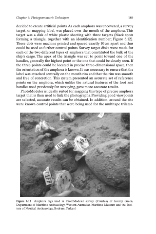
decided to create artificial points. As each amphora was uncovered, a survey target, or mapping label, was placed over the mouth of the amphora. This target was a disk of white plastic sheeting with three targets (black spots forming a triangle, together with an identification number; Figure 6.12). These dots were machine printed and spaced exactly 10 cm apart and thus could be used as further control points. Survey target disks were made for each of the two different types of amphora that constituted the bulk of the ship’s cargo. The apex of the triangle was set to point toward one of the handles, generally the highest point or the one that could be clearly seen. If the three points could be located in precise three-dimensional space, then the orientation of the amphora is known. It was necessary to ensure that the label was attached centrally on the mouth rim and that the rim was smooth and free of concretion. This system presented an accurate set of reference points on the amphora, which unlike the natural features of the foot and handles used previously for surveying, gave more accurate results.
PhotoModeler is ideally suited for mapping this type of precise amphora target that is then used to link the photographs. Providing good viewpoints are selected, accurate results can be obtained. In addition, around the site were known control points that were being used for the multitape trilater-
Figure 6.12 Amphora tags used in PhotoModeler survey. (Courtesy of Jeremy Green, Department of Maritime Archaeology, Western Australian Maritime Museum and the Insti- tute of Nautical Archaeology, Bodrum, Turkey.)
