
Page 106 - Nicolaes Witsen & Shipbuilding in the Dutch Golden Age
P. 106
Chapter Two
(76 II 25) 25. About the upper deck clamp.
1. The upper deck clamp be broad 19 inches.
2. Thick 3 inches.
(67 I 15) 2. The upper deck high 6 feet, and at the
heightof8feetittumbles 3feet:theotherforwardthe same, depending on the height.
The beams of the upper deck usually were lighter than those of the m ain deck: thick and broad w ith two thirds the thickness of the st em. The camber was stronger: five sixths the in side stem. They generally lay straight above the beams of the m ain deck, joining the futtoc k riders well and making the hatches lie straight in line with each other.
The upper dec k beams, however, were j oined to the ship in a c ompletely different way than the m ain deck beams. They were stuck between the frame timbers, tem- porarily supported with props in the middle and chocks in the sides. On ly then was the deck clamp a pplied under- neath. This method avoided a lot of measuring and mark- ing, but it sounds to us like it took a lot of messing around to get a smooth ru n to the dec k. The strong j oinery with dovetails, as f or the main dec k beams, was apparently considered superfluous for the upper decks.
45. Then make the deck clamp. (68 II 21) 17. About the upper deck clamp.
1. For the thickness of the upper deck clamp, 1⁄5 the thickness of the stem.
45. Then Make the Deck Clamp
The thickness of the upper deck clamp was only one fifth of the stem. As mentioned befor e, it was fi tted when the beams were already in place.
The forward and aft parts of the upper deck of the pinas lay a foot or so closer to the lower deck than the middle— forward because the main deck needed less height there (that part of the main dec k was used f or the c able tier), while the upper deck could do with some more headroom in the forecastle as it was the crew’s quarters.
More headroom was also needed in the stern for the steering place and the cabin above the gun room. So any- one going from the upper dec k into the forec astle or the steering place had to descend a step.
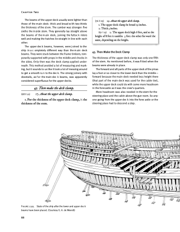
Figure 2.93. State of the ship after the lower and upper dec k beams have been placed. (Courtesy G. A. de Weerdt)
88
