
Page 30 - Loss of the VOC Retourschip Batavia, Western Australia, 1629
P. 30
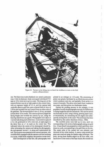
 Figure 18. Timbers in the lifting tray on board the workboat en·route to the field station at Beacon Island.
site. The lines were made ofplaited, low-stretch, polyester rope, 5 mm in diameter; these were taped with black PVC tape at 1/2 m intervals to give a scale. The long axis of !he camera format was set at right angles to the control lines, with an exposure height of 2.5 m, and the camera held vertically above a grid line, gave a lateral field of view of 2.38 m and included the two control lines on ei!her side of the grid line. The forward field of view (1.59 m), included at least three 1/2 m marks. The camera operator judged the flying height and levelled the camera by eye, using the framing attachment as a guide. Photographs were taken at 1mintervalsalongeachofthelines.Aseconddiverplaced a 2 m rod, graduated in 1/2 m intervals, at right angles to the three lines at a 1 m mark on the cenue line. This indicated where the centre of the photograph sbould be. After orientating the camera and taking the photographs, the rod-operator moved 1 m along and repositioned the rod. This system was essential as the camera operator, who would be fully engaged with the camera work and working in a surge, could easily misplace the position on the lines.
After development of the film, the photographs were
printed in an enlarger at 1:10 scale. The processing of prints was greatly facilitated by an Ilford process printer which produces semi-dry and partially fixed prints in a matter of seconds. The prints were batch fixed, washed in sea-water, and then given two freshwater rinses.
During the printing process in the enlarger, it was possible to rectify the photographs notonly for differences in flying height but also for camera till This can be carried out manually by trial, using a tilting, printing paper easel, or theoretically, by calculating the tilt angles and subse- quently setting them on the easeL This technique has been describedbythisauthorelsewhere(Green, 1980).
The rectified prints were laid up in runs, each run corresponding to the series of photographs along one grid line. A base-board was prepared on which grid lines were drawn to scale, corresponding to the grid lines on the site. The centre print of the central line was selected, and uimmed of any white borde~. A narrow suip around the print was removed using the feather-edge techrtique. The print, having been feather-edged on all four sides, was stuck down in the centre ofthe base-board, the central line
18
",. "
...1.
