
Page 31 - Loss of the VOC Retourschip Batavia, Western Australia, 1629
P. 31
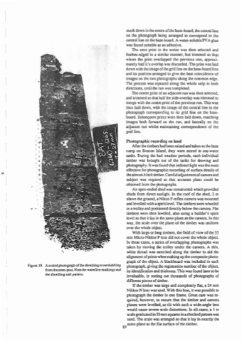
 Figure 19.
A scaled photograph of the sheathing or vudubbling from the stem·post. Note the waterline markings and the sheathing nail pal"'m.
stuck down in the centre of the base-board, the central line on the photograph being arranged to correspond to the central line on the base-board. A water-soluble PV A glue was found suitable as an adhesive.
The next print in the series was then selected and feather-edged in a similar manner, but trimmed so that where the print overlapped the previous one, approxi- mately half it's overlap was discarded. The print was laid down with the image of the grid line on the base-board line and its position arranged to give the best coincidence of images on the two photographs along the common edge. The process was repeated along the whole strip in both directions, until the run was completed.
The centre print of an adjacent run was then selected, and trimmed so that half the side-overlap was trimmed to merge with the centre print of the previous run. TIlls was then laid down, with the image of the central line in the photograph corresponding to its grid line on the base- board. Subsequent prints were then laid down, matching images both forward on the run, and laterally on the adjacent run whilst maintaining correspondence of the grid line.
Photographic recording on land
After the timbers had been raised and taken to the base
camp on Beacon Island, they were stored in sea-water tanks. During the bad weather periods, each individual timber was brought out of the tanks for drawing and photography. It was found that indirect light was the most effective for photographic recording of surface details of thealmost-blacktimber.Carefuladjustmentofcameraand subject was required so that accurate plans could be obtained from the photographs.
An open-ended shed was constructed which provided shade from direct sunlight. In the roof of the shed, 2 m above the ground, a Nikon F reflex camera was mounted and levelled with a spirit level. The timbers were wheeled in a trolley and positioned directly below the camera. Flat timbers were then levelled, also using a builder's spirit level so that it lay in the same plane as the camera. In this way, the scale over the plane of the timber was uniform over the whole object.
With large or long timber.;, the field of view of the 55 mm Micro·Nikkor P lens did not cover the whole object. In these cases, a series of overlapping photographs was taken by moving the trolley under the camera. A thin, white thread was stretched along the timber to aid the alignment ofprints when making up the composite photo- graph of the object A blackboard was included in each photograph, giving the registration number of the object, its identification and thickness. This was found later to be invaluable, in sorting out thousands of photographs of different pieces of timber.
If the timber was large and completely fla~ a 24 mm Nikkor N lens was used. With this lens, it was possible to photograph the timber in one frame. Great care was re- quired, however, to ensure that the timber and camera planes were levelled, as tilt with such a wide-angle lens would cause severe scale distortions. In all cases, a I m scale graduated in 20 mm squares in a checked pauem was used. The scale was arranged so that it lay in exactly the
19 same plane as the flat surface of the timber.
