
Page 19 - TVH 2000 Anniversary Shipwreck Project
P. 19
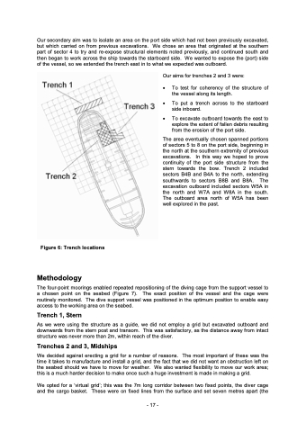
Our secondary aim was to isolate an area on the port side which had not been previously excavated, but which carried on from previous excavations. We chose an area that originated at the southern part of sector 4 to try and re-expose structural elements noted previously, and continued south and then began to work across the ship towards the starboard side. We wanted to expose the (port) side of the vessel, so we extended the trench east in to what we expected was outboard. Our aims for trenches 2 and 3 were: • To test for coherency of the structure of the vessel along its length. • To put a trench across to the starboard side inboard. • To excavate outboard towards the east to explore the extent of fallen debris resulting from the erosion of the port side. The area eventually chosen spanned portions of sectors 5 to 8 on the port side, beginning in the north at the southern extremity of previous excavations. In this way we hoped to prove continuity of the port side structure from the stern towards the bow. Trench 2 included sectors B4B and B4A to the north, extending southwards to sectors B8B and B8A. The excavation outboard included sectors W5A in the north and W7A and W8A in the south. The outboard area north of W5A has been well explored in the past. Figure 6: Trench locations Methodology The four-point moorings enabled repeated repositioning of the diving cage from the support vessel to a chosen point on the seabed (Figure 7). The exact position of the vessel and the cage were routinely monitored. The dive support vessel was positioned in the optimum position to enable easy access to the working area on the seabed. Trench 1, Stern As we were using the structure as a guide, we did not employ a grid but excavated outboard and downwards from the stern post and transom. This was satisfactory, as the distance away from intact structure was never more than 2m, within reach of the diver. Trenches 2 and 3, Midships We decided against erecting a grid for a number of reasons. The most important of these was the time it takes to manufacture and install a grid, and the fact that we did not want an obstruction left on the seabed should we have to move for weather. We also wanted flexibility to move our work area; this is a much harder decision to make once such a huge investment is made in making a grid. We opted for a ‘virtual grid’; this was the 7m long corridor between two fixed points, the diver cage and the cargo basket. These were on fixed lines from the surface and set seven metres apart (the - 17 -
