
Page 110 - The ROV Manual - A User Guide for Remotely Operated Vehicles 2nd edition
P. 110
98 CHAPTER 4 Vehicle Control and Simulation
CB
CG
Stationary ROV
Water flow
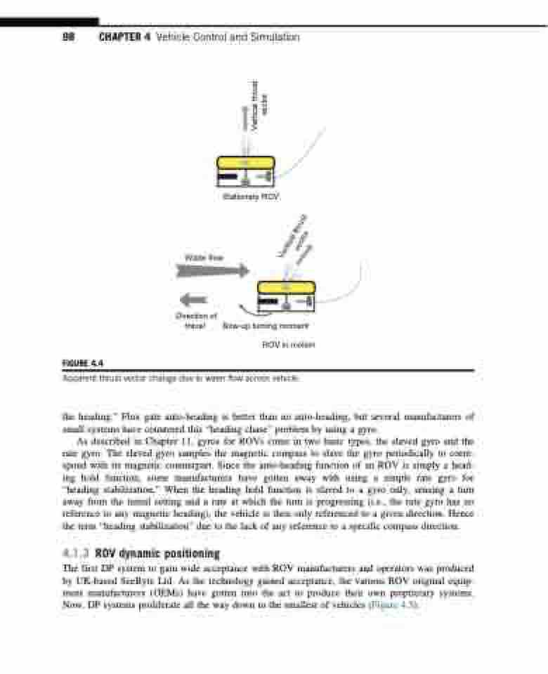
FIGURE 4.4
Direction of travel
CB
CG
Bow-up turning moment
ROV in motion
Apparent thrust vector change due to water flow across vehicle.
the heading.” Flux gate auto-heading is better than no auto-heading, but several manufacturers of small systems have countered this “heading chase” problem by using a gyro.
As described in Chapter 11, gyros for ROVs come in two basic types, the slaved gyro and the rate gyro. The slaved gyro samples the magnetic compass to slave the gyro periodically to corre- spond with its magnetic counterpart. Since the auto-heading function of an ROV is simply a head- ing hold function, some manufacturers have gotten away with using a simple rate gyro for “heading stabilization.” When the heading hold function is slaved to a gyro only, sensing a turn away from the initial setting and a rate at which the turn is progressing (i.e., the rate gyro has no reference to any magnetic heading), the vehicle is then only referenced to a given direction. Hence the term “heading stabilization” due to the lack of any reference to a specific compass direction.
4.1.3 ROV dynamic positioning
The first DP system to gain wide acceptance with ROV manufacturers and operators was produced by UK-based SeeByte Ltd. As the technology gained acceptance, the various ROV original equip- ment manufacturers (OEMs) have gotten into the act to produce their own proprietary systems. Now, DP systems proliferate all the way down to the smallest of vehicles (Figure 4.5).
Vertical thrust vector
Vertical thrust vector
