
Page 114 - The ROV Manual - A User Guide for Remotely Operated Vehicles 2nd edition
P. 114
102 CHAPTER 4 Vehicle Control and Simulation
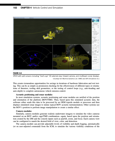
FIGURE 4.6
VROV with split screens including “God’s eye” 3D external view, forward camera, and multibeam sonar displays.
(Courtesy Soil Machine Dynamics Ltd. (SMD) and GRI Simulations Inc.)
This creates tremendous opportunities for savings in iterations of hardware fabrication and wet test- ing. This can be as simple as premission checking for the effectiveness of different types or orienta- tions of thrusters, tooling skid geometries, or the testing of control loops (e.g., auto-heading and auto-depth) to complete autonomous vehicle mission control.
Acoustic positioning and sonar modules
In most simulation systems, acoustic positioning and sonar modules are notified of the position and orientation of the platform (ROV/TMS). Then, based upon this simulated acoustic data, the software either sends this data to be processed by an OEM topside module or processes and then displays simulated sonar images to mimic typical ROV acoustic instrumentation. Other systems use the ROV’s position to perform image manipulation to create a similar effect.
Camera modules
Similarly, camera modules generate realistic underwater imagery to simulate the video cameras mounted on an ROV and/or cage/TMS combination—again, based upon the position and orienta- tion created by the DM and the console inputs such as pan/tilt, zoom, and focus. Each camera view can be configured to match the desired field of view, color, and distortion.
The camera module can provide adjustable levels of visibility and depth fogging, automatically (or on user-adjusted command) from the ICM, to simulate the various visibility conditions of the
