
Page 116 - The ROV Manual - A User Guide for Remotely Operated Vehicles 2nd edition
P. 116
104 CHAPTER 4 Vehicle Control and Simulation
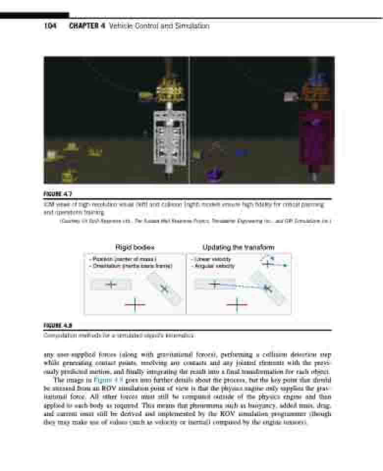
FIGURE 4.7
ICM views of high-resolution visual (left) and collision (right) models ensure high fidelity for critical planning and operations training.
(Courtesy Oil Spill Response Ltd., The Subsea Well Response Project, Trendsetter Engineering Inc., and GRI Simulations Inc.)
Rigid bodies Updating the transform
- Position (center of mass )
- Orientation (inertia basis frame)
- Linear velocity
- Angular velocity
FIGURE 4.8
Computation methods for a simulated object’s kinematics.
any user-supplied forces (along with gravitational forces), performing a collision detection step while generating contact points, resolving any contacts and any jointed elements with the previ- ously predicted motion, and finally integrating the result into a final transformation for each object.
The image in Figure 4.9 goes into further details about the process, but the key point that should be stressed from an ROV simulation point of view is that the physics engine only supplies the grav- itational force. All other forces must still be computed outside of the physics engine and then applied to each body as required. This means that phenomena such as buoyancy, added mass, drag, and current must still be derived and implemented by the ROV simulation programmer (though they may make use of values (such as velocity or inertial) computed by the engine tensors).
