
Page 131 - The ROV Manual - A User Guide for Remotely Operated Vehicles 2nd edition
P. 131
Righting moment
P
W
θ
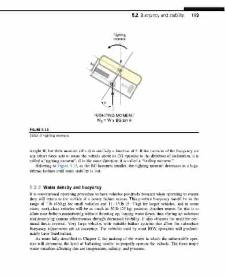
RIGHTING MOMENT M0 = W x BG sin θ
5.2 Buoyancy and stability 119
FIGURE 5.13
Detail of righting moment.
weight W, but their moment (W 3 d) is similarly a function of θ. If the moment of the buoyancy (or any other) force acts to rotate the vehicle about its CG opposite to the direction of inclination, it is called a “righting moment”; if in the same direction, it is called a “heeling moment.”
Referring to Figure 5.13, as the BG becomes smaller, the righting moment decreases in a loga- rithmic fashion until static stability is lost.
5.2.3 Water density and buoyancy
It is conventional operating procedure to have vehicles positively buoyant when operating to ensure they will return to the surface if a power failure occurs. This positive buoyancy would be in the range of 1 lb (450 g) for small vehicles and 1115 lb (57 kg) for larger vehicles, and in some cases, work-class vehicles will be as much as 50 lb (23 kg) positive. Another reason for this is to allow near-bottom maneuvering without thrusting up, forcing water down, thus stirring up sediment and destroying camera effectiveness through decreased visibility. It also obviates the need for con- tinual thrust reversal. Very large vehicles with variable ballast systems that allow for subsurface buoyancy adjustments are an exception. The vehicles used by most ROV operators will predomi- nantly have fixed ballast.
As more fully described in Chapter 2, the makeup of the water in which the submersible oper- ates will determine the level of ballasting needed to properly operate the vehicle. The three major water variables affecting this are temperature, salinity, and pressure.
BG
CB
CG
