
Page 136 - The ROV Manual - A User Guide for Remotely Operated Vehicles 2nd edition
P. 136
124 CHAPTER 6 Thrusters
every 50100 hours of operation. This increased the inventory of parts required and the possibili- ties of errors by the technicians in reassembling the motors. Thus, investing in a reliable design from the beginning can save both time and money.
The propulsion system has to be a trade-off between what the ROV requires for the performance of a work task and the practical dimensions of the ROV. Typically, the more the thruster power required, the heavier the equipment on the ROV. All parts of the ROV system will grow exponen- tially larger with the power requirement continuing to increase. Thus, observation ROVs are nor- mally restricted to a few minor work tasks without major modifications that would move them to the next heavier class. As the work tasks increase, so does the size of the vehicle and thus the size of the thruster system. The goal is to design an efficient thruster system with minimal (and easily repairable) components. A good example of such a system for a hydraulically operated heavy work-class vehicle is that of Schilling’s HD vehicle (Figure 6.1). The hydraulic pumps are designed for easy removal and replacement on the drive motor.
6.1.2 Thruster basics
The ROV’s propulsion system is made up of two or more thrusters that propel the vehicle in a man- ner that allows navigation to the work site. Thrusters must be positioned on the vehicle so that the moment arm of their thrust force, relative to the central mass of the vehicle, allows a proper amount of maneuverability and controllability.
Thrust vectoring is the only means of locomotion for an ROV. There are numerous placement options for thrusters to allow varying degrees of maneuverability. Maneuvering is achieved through asymmetrical thrusting based upon thruster placement as well as varying thruster output.
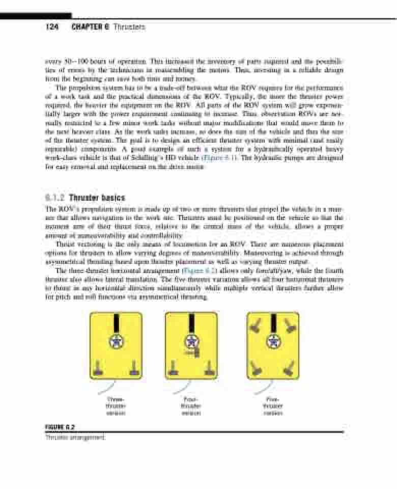
The three-thruster horizontal arrangement (Figure 6.2) allows only fore/aft/yaw, while the fourth thruster also allows lateral translation. The five-thruster variation allows all four horizontal thrusters to thrust in any horizontal direction simultaneously while multiple vertical thrusters further allow for pitch and roll functions via asymmetrical thrusting.
FIGURE 6.2
Thruster arrangement.
Three- thruster version
Four- thruster version
Five- thruster version
