
Page 242 - The ROV Manual - A User Guide for Remotely Operated Vehicles 2nd edition
P. 242
9.2 TMS-based vehicle deployment techniques 231
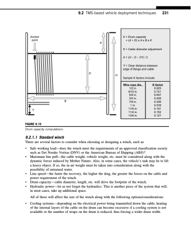
X = Drum capacity
= (A + D) x A x B x K
K = Cable diameter adjustment A = (H – D – 2Y) / 2
Y = Clear distance between edge of flange and cable
Sample K factors Include:
Wire rope dia.
1/2 in. 9/16 in. 5/8 in. 3/4 in. 7/8 in. 1 in. 11/8 in. 11/4 in. 13/8 in.
K factor
0.925 0.741 0.607 0.428 0.308 0.239 0.191 0.152 0.127
Anchor point
A
H
Drum capacity computations.
9.2.1.1 Standard winch
B
D
Y
FIGURE 9.10
There are several factors to consider when choosing or designing a winch, such as:
• Safe working load—does the winch meet the requirements of an approved classification society such as Det Norske Veritas (DNV) or the American Bureau of Shipping (ABS)?
• Maximum line pull—the cable weight, vehicle weight, etc. must be considered along with the dynamic forces induced by Mother Nature. Also, in some cases, the vehicle’s task may be to lift a heavy object. If so, the in-air weight must be taken into consideration along with the possibility of entrained water.
• Line speed—the faster the recovery, the higher the drag, the greater the forces on the cable and power requirement of the winch.
• Drum capacity—cable diameter, length, etc. will drive the footprint of the winch.
• Hydraulic power—let us not forget the hydraulics. This is another piece of the system that will,
in most cases, take up additional space.
All of these will affect the size of the winch along with the following options/considerations:
• Cooling systems—depending on the electrical power being transmitted down the cable, heating of the internal layers of the cable on the drum can become excessive if a cooling system is not available or the number of wraps on the drum is reduced, thus forcing a wider drum width.
