
Page 282 - The ROV Manual - A User Guide for Remotely Operated Vehicles 2nd edition
P. 282
(a) (b)
10.3 Digital video 271
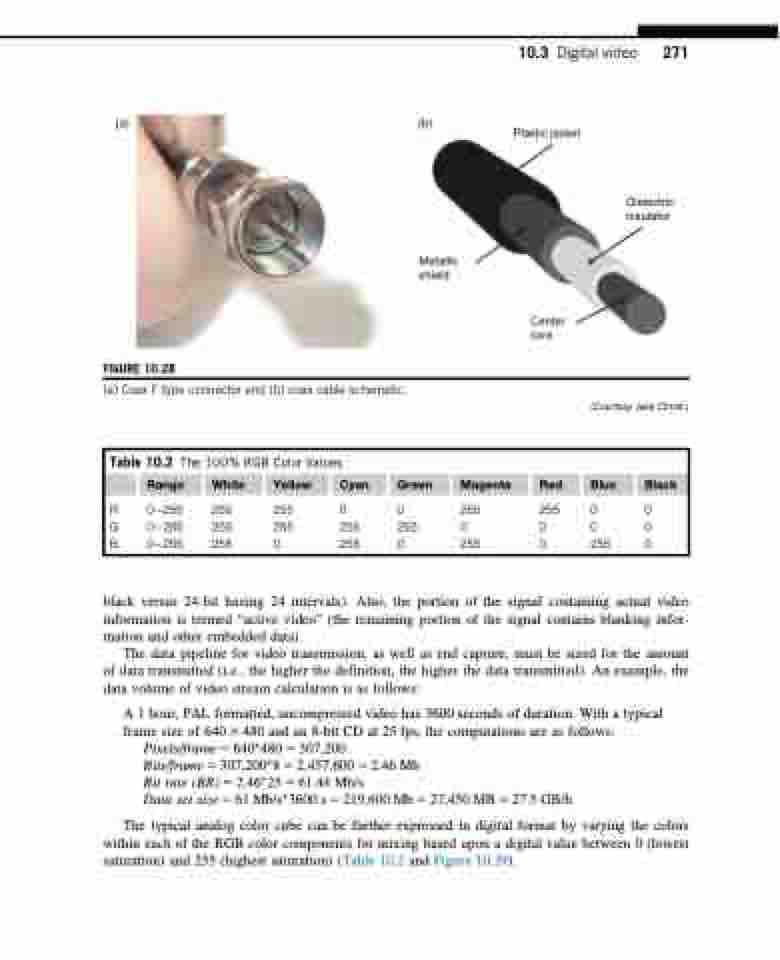
Plastic jacket
Dielectric insulator
Metallic shield
FIGURE 10.28
(a) Coax F-type connector and (b) coax cable schematic.
Center core
(Courtesy Jake Christ.)
Table 10.2 The 100% RGB Color Values
Range White Yellow Cyan Green Magenta Red Blue Black
R 0255 255 255 0 0 255 G 0255 255 255 255 255 0
255 0 0 0 0 0 0 255 0
B 0255 255 0
255 0 255
black versus 24-bit having 24 intervals). Also, the portion of the signal containing actual video information is termed “active video” (the remaining portion of the signal contains blanking infor- mation and other embedded data).
The data pipeline for video transmission, as well as end capture, must be sized for the amount of data transmitted (i.e., the higher the definition, the higher the data transmitted). An example, the data volume of video stream calculation is as follows:
A 1 hour, PAL formatted, uncompressed video has 3600 seconds of duration. With a typical frame size of 640 3 480 and an 8-bit CD at 25 fps, the computations are as follows:
Pixels/frame 5 640 480 5 307,200
Bits/frame 5 307,200 8 5 2,457,600 5 2.46 Mb
Bit rate (BR) 5 2.46 25 5 61.44 Mb/s
Data set size 5 61 Mb/s3600 s 5 219,600 Mb 5 27,450 MB 5 27.5 GB/h
The typical analog color cube can be further expressed in digital format by varying the colors within each of the RGB color components for mixing based upon a digital value between 0 (lowest saturation) and 255 (highest saturation) (Table 10.2 and Figure 10.29).
