
Page 343 - The ROV Manual - A User Guide for Remotely Operated Vehicles 2nd edition
P. 343
13.2 Transmission 335
1
0
1
0
FIGURE 13.4
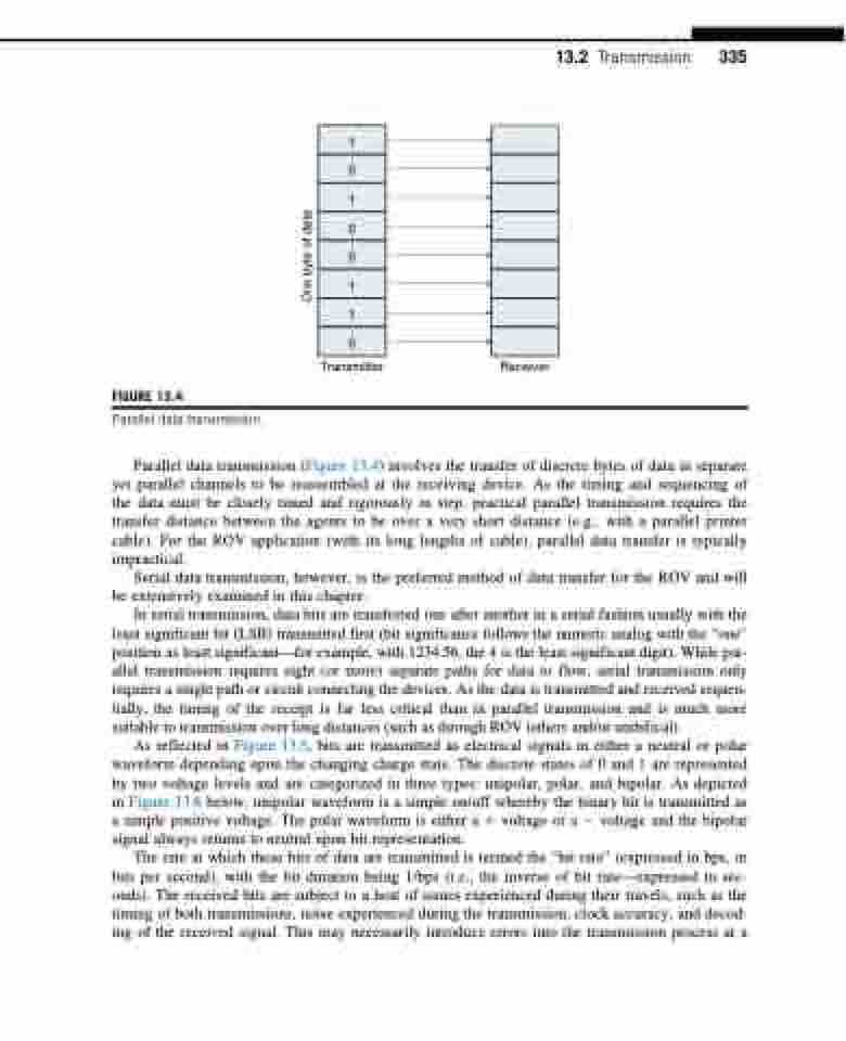
Parallel data transmission.
0
1
1
0
Transmitter Receiver
Parallel data transmission (Figure 13.4) involves the transfer of discrete bytes of data in separate yet parallel channels to be reassembled at the receiving device. As the timing and sequencing of the data must be closely timed and rigorously in step, practical parallel transmission requires the transfer distance between the agents to be over a very short distance (e.g., with a parallel printer cable). For the ROV application (with its long lengths of cable), parallel data transfer is typically impractical.
Serial data transmission, however, is the preferred method of data transfer for the ROV and will be extensively examined in this chapter.
In serial transmission, data bits are transferred one after another in a serial fashion usually with the least significant bit (LSB) transmitted first (bit significance follows the numeric analog with the “one” position as least significant—for example, with 1234.56, the 4 is the least significant digit). While par- allel transmission requires eight (or more) separate paths for data to flow, serial transmission only requires a single path or circuit connecting the devices. As the data is transmitted and received sequen- tially, the timing of the receipt is far less critical than in parallel transmission and is much more suitable to transmission over long distances (such as through ROV tethers and/or umbilical).
As reflected in Figure 13.5, bits are transmitted as electrical signals in either a neutral or polar waveform depending upon the changing charge state. The discrete states of 0 and 1 are represented by two voltage levels and are categorized in three types: unipolar, polar, and bipolar. As depicted in Figure 13.6 below, unipolar waveform is a simple on/off whereby the binary bit is transmitted as a simple positive voltage. The polar waveform is either a 1 voltage or a 2 voltage and the bipolar signal always returns to neutral upon bit representation.
The rate at which these bits of data are transmitted is termed the “bit rate” (expressed in bps, or bits per second), with the bit duration being 1/bps (i.e., the inverse of bit rate—expressed in sec- onds). The received bits are subject to a host of issues experienced during their travels, such as the timing of both transmissions, noise experienced during the transmission, clock accuracy, and decod- ing of the received signal. This may necessarily introduce errors into the transmission process at a
One byte of data
