
Page 344 - The ROV Manual - A User Guide for Remotely Operated Vehicles 2nd edition
P. 344
336 CHAPTER 13 Communications
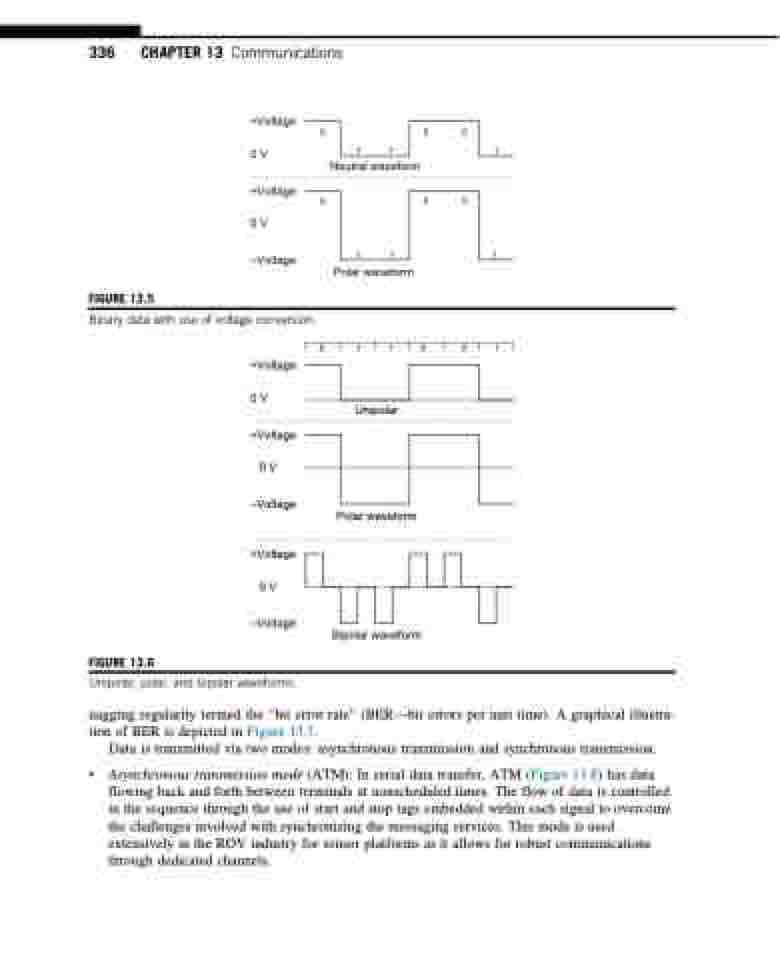
FIGURE 13.5
+Voltage
0V
+Voltage 0V
–Voltage
000 111
Neutral waveform 000
111 Polar waveform
011001
Unipolar
Polar waveform
Bipolar waveform
Binary data with use of voltage conversion.
+Voltage
0V
+Voltage 0V
–Voltage
+Voltage 0V
–Voltage
FIGURE 13.6
Unipolar, polar, and bipolar waveforms.
nagging regularity termed the “bit error rate” (BER—bit errors per unit time). A graphical illustra- tion of BER is depicted in Figure 13.7.
Data is transmitted via two modes: asynchronous transmission and synchronous transmission.
• Asynchronous transmission mode (ATM): In serial data transfer, ATM (Figure 13.8) has data flowing back and forth between terminals at nonscheduled times. The flow of data is controlled in the sequence through the use of start and stop tags embedded within each signal to overcome the challenges involved with synchronizing the messaging services. This mode is used extensively in the ROV industry for sensor platforms as it allows for robust communications through dedicated channels.
