
Page 360 - The ROV Manual - A User Guide for Remotely Operated Vehicles 2nd edition
P. 360
352 CHAPTER 13 Communications
FIGURE 13.26
Comparison of LED to laser frequency response.
Fiber
Fusion splice
Fiber
Mechanical splice
Fiber
Index matching gel
Fiber
LED
Laser Wavelength
Electric arc
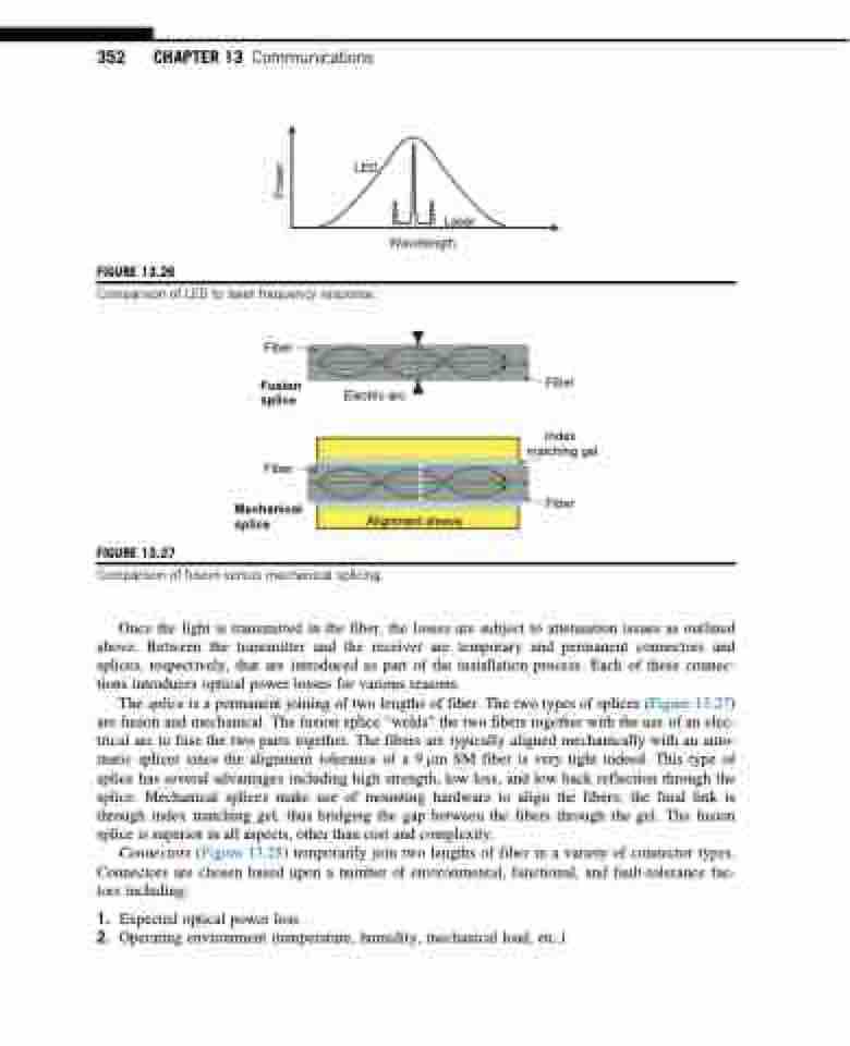
FIGURE 13.27
Alignment sleeve
Comparison of fusion versus mechanical splicing.
Once the light is transmitted in the fiber, the losses are subject to attenuation issues as outlined above. Between the transmitter and the receiver are temporary and permanent connectors and splices, respectively, that are introduced as part of the installation process. Each of these connec- tions introduces optical power losses for various reasons.
The splice is a permanent joining of two lengths of fiber. The two types of splices (Figure 13.27) are fusion and mechanical. The fusion splice “welds” the two fibers together with the use of an elec- trical arc to fuse the two parts together. The fibers are typically aligned mechanically with an auto- matic splicer since the alignment tolerance of a 9 μm SM fiber is very tight indeed. This type of splice has several advantages including high strength, low loss, and low back reflection through the splice. Mechanical splices make use of mounting hardware to align the fibers; the final link is through index matching gel, thus bridging the gap between the fibers through the gel. The fusion splice is superior in all aspects, other than cost and complexity.
Connectors (Figure 13.28) temporarily join two lengths of fiber in a variety of connector types. Connectors are chosen based upon a number of environmental, functional, and fault-tolerance fac- tors including:
1. Expected optical power loss
2. Operating environment (temperature, humidity, mechanical load, etc.)
Power
