
Page 362 - The ROV Manual - A User Guide for Remotely Operated Vehicles 2nd edition
P. 362
354 CHAPTER 13 Communications
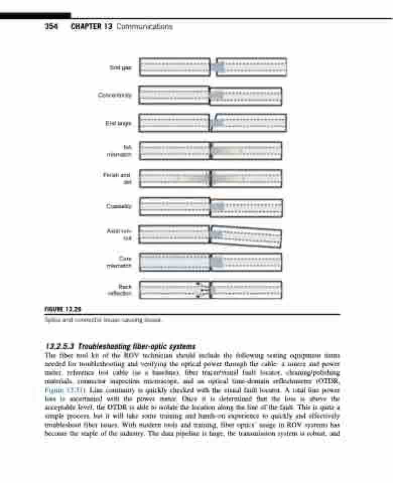
FIGURE 13.29
End gap
Concentricity
End angle
NA mismatch
Finish and dirt
Coaxiality
Axial run- out
Core mismatch
Back reflection
Splice and connector issues causing losses.
13.2.5.3 Troubleshooting fiber-optic systems
The fiber tool kit of the ROV technician should include the following testing equipment items needed for troubleshooting and verifying the optical power through the cable: a source and power meter, reference test cable (as a baseline), fiber tracer/visual fault locator, cleaning/polishing materials, connector inspection microscope, and an optical time-domain reflectometer (OTDR, Figure 13.31). Line continuity is quickly checked with the visual fault locator. A total line power loss is ascertained with the power meter. Once it is determined that the loss is above the acceptable level, the OTDR is able to isolate the location along the line of the fault. This is quite a simple process, but it will take some training and hands-on experience to quickly and effectively troubleshoot fiber issues. With modern tools and training, fiber optics’ usage in ROV systems has become the staple of the industry. The data pipeline is huge, the transmission system is robust, and
