
Page 364 - The ROV Manual - A User Guide for Remotely Operated Vehicles 2nd edition
P. 364
356 CHAPTER 13 Communications
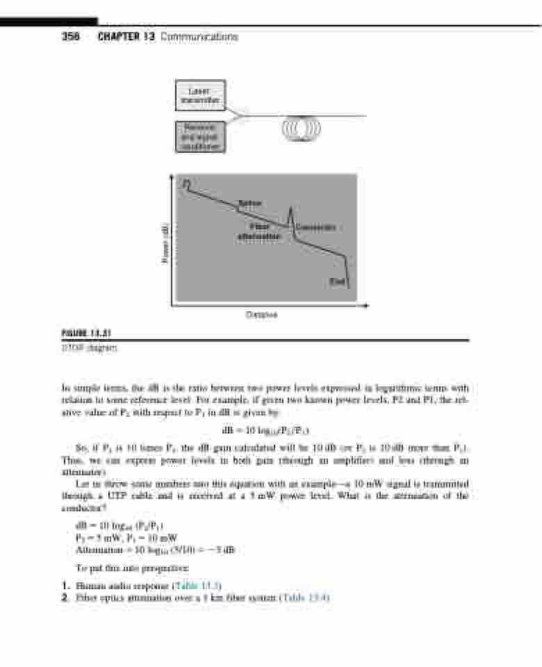
Laser transmitter
Receiver and signal conditioner
Splice
Fiber Connector attenuation
End
FIGURE 13.31
OTDR diagram.
Distance
In simple terms, the dB is the ratio between two power levels expressed in logarithmic terms with relation to some reference level. For example, if given two known power levels, P2 and P1, the rel- ative value of P2 with respect to P1 in dB is given by:
dB 5 10 log10ðP2=P1Þ
So, if P2 is 10 times P1, the dB gain calculated will be 10 dB (or P2 is 10 dB more than P1). Thus, we can express power levels in both gain (through an amplifier) and loss (through an attenuator).
Let us throw some numbers into this equation with an example—a 10 mW signal is transmitted through a UTP cable and is received at a 5 mW power level. What is the attenuation of the conductor?
dB510log10 (P2/P1)
P2 5 5 mW, P1 5 10 mW Attenuation510log10 (5/10)523dB
To put this into perspective:
1. Human audio response (Table 13.3)
2. Fiber optics attenuation over a 1 km fiber system (Table 13.4)
Power (dB)
