
Page 365 - The ROV Manual - A User Guide for Remotely Operated Vehicles 2nd edition
P. 365
13.2 Transmission 357
Table 13.3 Human Audio Response
Sound Type Sound Power Level
Hearing threshold (reference) Whisper
Air-conditioner
Two-person conversation Rush-hour traffic
Jet aircraft
Led Zeppelin concert
0 dB
130 dB
150 2 70 dB 150 2 70 dB 160 2 85 dB 1120 2 140 dB
.1130 dB
Table 13.4 Fiber-Optic System Component Attenuation
Source Type Power Level
Transmitter (reference) Fiber attenuation
6 Connectors
2 Splices
Total loss from transmitter to receiver
0 dB
20.5 dB/km @ 1310 or 1550 nm 20.75 dB per connector or 24.5 dB 20.3 dB per splice or 20.6 dB
25.6 dB
Table 13.5 Reference dB Power Levels for Optical Circuits
dBm Watts
dBm Watts
110 10 mW (milliwatts) 13 2 mW
0 1 mW
23 500 μW (microwatts) 26 250 μW
210 100 μW
220 10 μW
230 1μW
240 100 nW (nanowatts) 250 10 nW
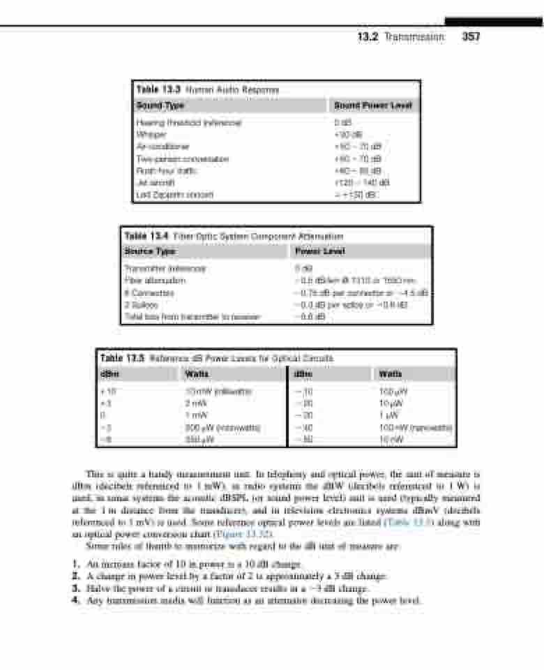
This is quite a handy measurement unit. In telephony and optical power, the unit of measure is dBm (decibels referenced to 1 mW), in radio systems the dBW (decibels referenced to 1 W) is used, in sonar systems the acoustic dBSPL (or sound power level) unit is used (typically measured at the 1 m distance from the transducer), and in television electronics systems dBmV (decibels referenced to 1 mV) is used. Some reference optical power levels are listed (Table 13.5) along with an optical power conversion chart (Figure 13.32).
Some rules of thumb to memorize with regard to the dB unit of measure are:
1. An increase factor of 10 in power is a 10 dB change.
2. A change in power level by a factor of 2 is approximately a 3 dB change.
3. Halve the power of a circuit or transducer results in a 23 dB change.
4. Any transmission media will function as an attenuator decreasing the power level.
