
Page 382 - The ROV Manual - A User Guide for Remotely Operated Vehicles 2nd edition
P. 382
374 CHAPTER 14 Underwater Acoustics
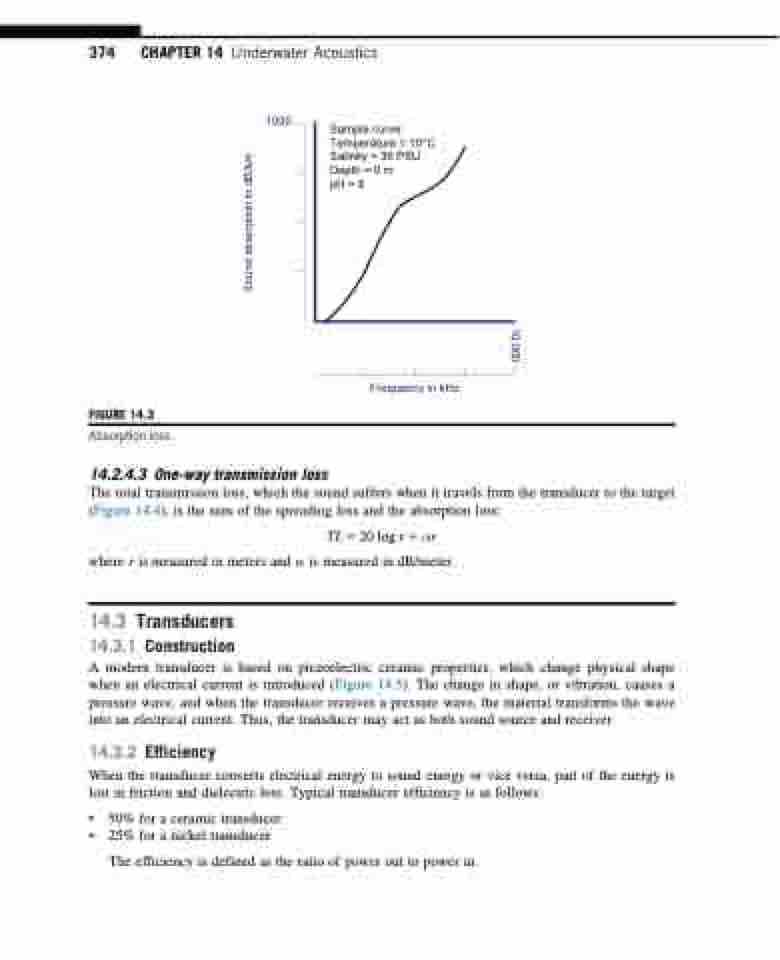
FIGURE 14.3
Absorption loss.
14.2.4.3 One-way transmission loss
1000
Sample curve: Temperature = 10°C Salinity = 35 PSU Depth = 0 m
pH = 8
Frequency in kHz
The total transmission loss, which the sound suffers when it travels from the transducer to the target (Figure 14.4), is the sum of the spreading loss and the absorption loss:
TL520 log r1αr where r is measured in meters and α is measured in dB/meter.
14.3 Transducers
14.3.1 Construction
A modern transducer is based on piezoelectric ceramic properties, which change physical shape when an electrical current is introduced (Figure 14.5). The change in shape, or vibration, causes a pressure wave, and when the transducer receives a pressure wave, the material transforms the wave into an electrical current. Thus, the transducer may act as both sound source and receiver.
14.3.2 Efficiency
When the transducer converts electrical energy to sound energy or vice versa, part of the energy is
lost in friction and dielectric loss. Typical transducer efficiency is as follows:
• 50% for a ceramic transducer
• 25% for a nickel transducer
The efficiency is defined as the ratio of power out to power in.
Sound absorption in dB/km
10,000
