
Page 383 - The ROV Manual - A User Guide for Remotely Operated Vehicles 2nd edition
P. 383
200
180
160
140
120
100
80 60 40
0.1 0.2 0.5 1 2 5 10 20 50 100
Distance (r)
100 50 30 10 5 kHz kHz kHz kHz kHz
1 kHz
Spreading loss
km
14.3 Transducers 375
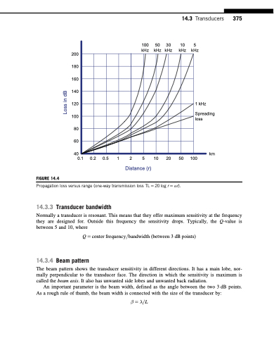
FIGURE 14.4
Propagation loss versus range (one-way transmission loss TL 5 20 log r 5 αr).
14.3.3 Transducer bandwidth
Normally a transducer is resonant. This means that they offer maximum sensitivity at the frequency they are designed for. Outside this frequency the sensitivity drops. Typically, the Q-value is between 5 and 10, where
Q 5 center frequency=bandwidth ðbetween 3 dB pointsÞ
14.3.4 Beam pattern
The beam pattern shows the transducer sensitivity in different directions. It has a main lobe, nor- mally perpendicular to the transducer face. The direction in which the sensitivity is maximum is called the beam axis. It also has unwanted side lobes and unwanted back radiation.
An important parameter is the beam width, defined as the angle between the two 3 dB points. As a rough rule of thumb, the beam width is connected with the size of the transducer by:
β5λ=L
Loss in dB
