
Page 385 - The ROV Manual - A User Guide for Remotely Operated Vehicles 2nd edition
P. 385
–10 dB
–20
–30
–40
–4 –3 –2 –1 0 1 2 3 4
FIGURE 14.6
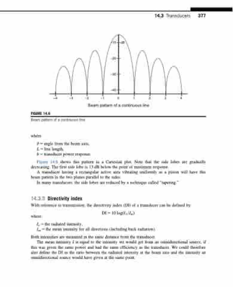
Beam pattern of a continuous line.
where
Beam pattern of a continuous line
14.3 Transducers 377
θ 5 angle from the beam axis, L 5 line length,
b 5 transducer power response.
Figure 14.6 shows this pattern in a Cartesian plot. Note that the side lobes are gradually decreasing. The first side lobe is 13 dB below the point of maximum response.
A transducer having a rectangular active area vibrating uniformly as a piston will have this beam pattern in the two planes parallel to the sides.
In many transducers, the side lobes are reduced by a technique called “tapering.”
14.3.5 Directivity index
With reference to transmission, the directivity index (DI) of a transducer can be defined by:
DI 5 10 logðIo=ImÞ
Im 5 the mean intensity for all directions (including back radiation).
where
Io 5 the radiated intensity,
Both intensities are measured in the same distance from the transducer.
The mean intensity I is equal to the intensity we would get from an omnidirectional source, if
this was given the same power and had the same efficiency as the transducer. We could therefore also define the DI as the ratio between the radiated intensity at the beam axis and the intensity an omnidirectional source would have given at the same point.
