
Page 386 - The ROV Manual - A User Guide for Remotely Operated Vehicles 2nd edition
P. 386
378 CHAPTER 14 Underwater Acoustics
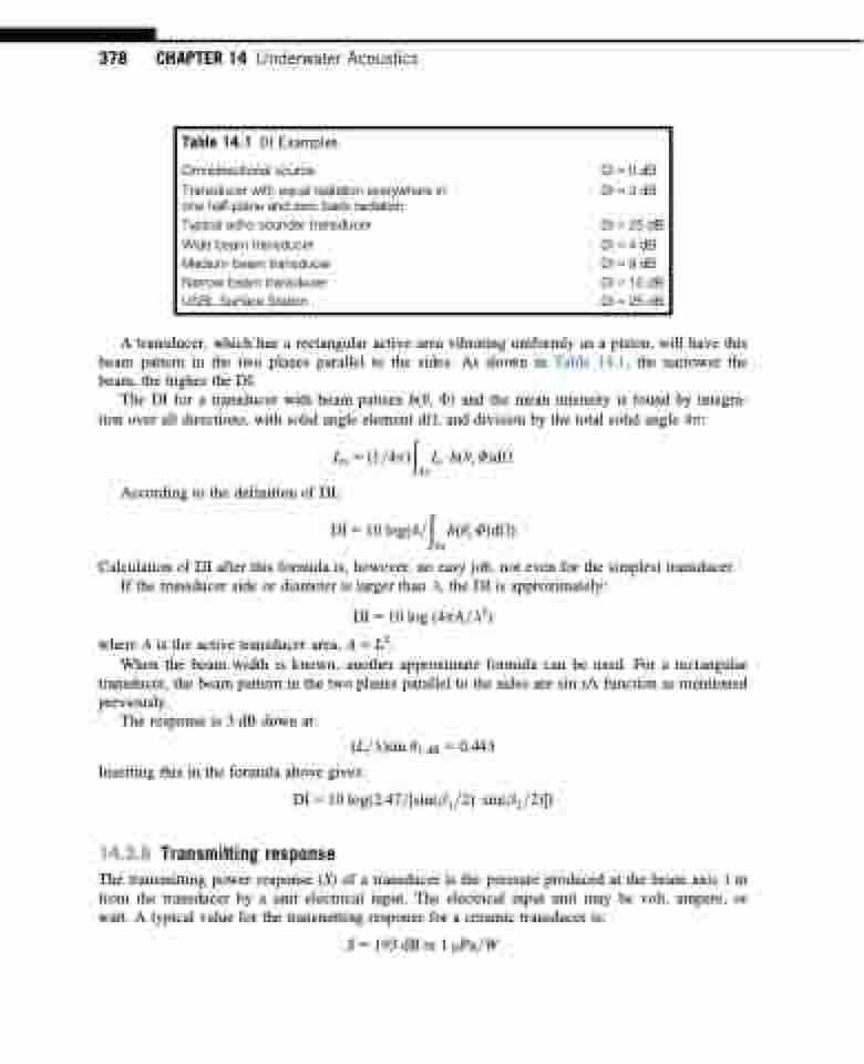
Table 14.1 DI Examples
Omnidirectional source
Transducer with equal radiation everywhere in one half-plane and zero back radiation Typical echo sounder transducer
Wide beam transducer
Medium beam transducer
Narrow beam transducer
USBL Surface Station
DI 5 0 dB DI 5 3 dB
DI 5 25 dB DI 5 4 dB DI 5 9 dB DI 5 15 dB DI 5 25 dB
A transducer, which has a rectangular active area vibrating uniformly as a piston, will have this beam pattern in the two planes parallel to the sides. As shown in Table 14.1, the narrower the beam, the higher the DI.
The DI for a transducer with beam pattern b(θ, Φ) and the mean intensity is found by integra- tion over all directions, with solid angle element dΩ, and division by the total solid angle 4π:
ð
4π
Im 5 ð1=4πÞ According to the definition of DI:
IoUbðθ; ΦÞdΩ ð
DI 5 10 logð4=
Calculation of DI after this formula is, however, no easy job, not even for the simplest transducer.
bðθ; ΦÞdΩÞ
If the transducer side or diameter is larger than λ, the DI is approximately:
transducer, the beam pattern in the two planes parallel to the sides are sin x/x function as mentioned previously.
The response is 3 dB down at: Inserting this in the formula above gives:
DI 5 10 log ð4πA=λ2Þ 2
where A is the active transducer area, A 5 L .
When the beam width is known, another approximate formula can be used. For a rectangular
ðL=λÞsin θ3 dB 5 0:443
DI 5 10 logð2:47=1⁄2sinðβ1=2ÞUsinðβ2=2ÞÞ
14.3.6 Transmitting response
The transmitting power response (S) of a transducer is the pressure produced at the beam axis 1 m from the transducer by a unit electrical input. The electrical input unit may be volt, ampere, or watt. A typical value for the transmitting response for a ceramic transducer is:
S5193 dB re 1 μPa=W
4π
