
Page 412 - The ROV Manual - A User Guide for Remotely Operated Vehicles 2nd edition
P. 412
(b)
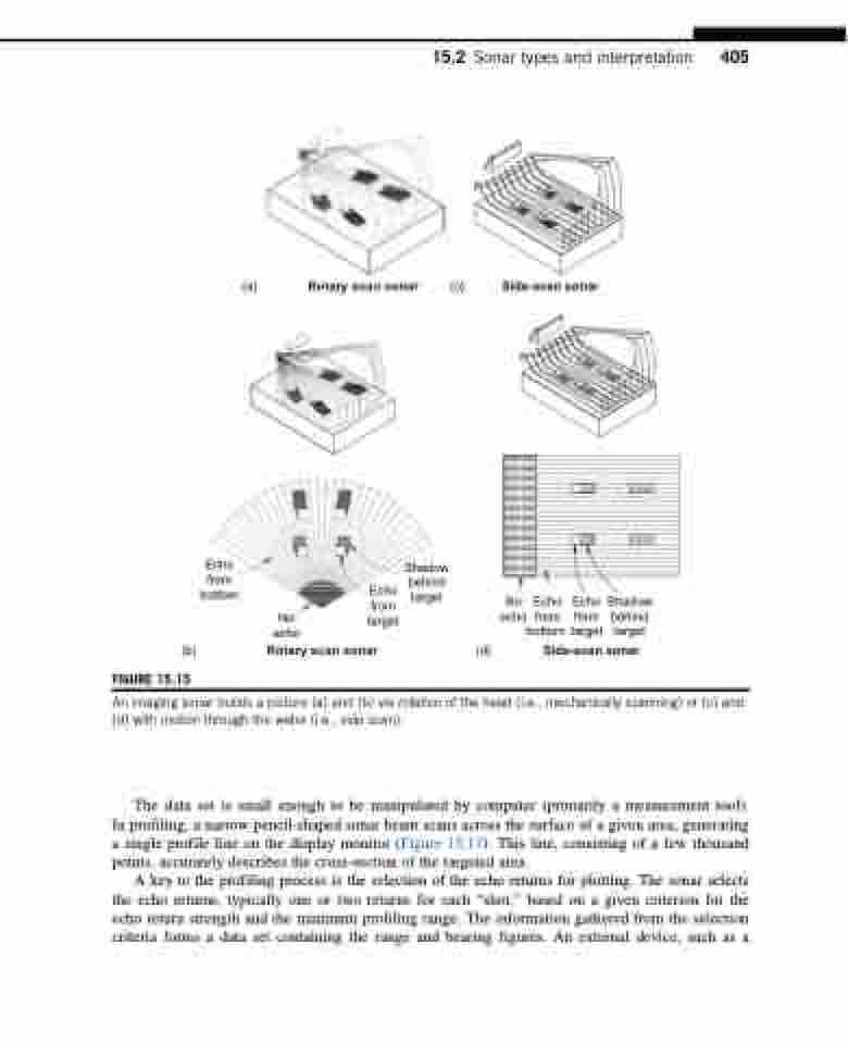
FIGURE 15.15
Rotary scan sonar
(d)
Echo from bottom
Shadow
Echo target from
target
(a)
Rotary scan sonar (c)
Side-scan sonar
No echo
No Echo Echo Shadow echo from from behind bottom target target
Side-scan sonar
behind
15.2 Sonar types and interpretation 405
An imaging sonar builds a picture (a) and (b) via rotation of the head (i.e., mechanically scanning) or (c) and (d) with motion through the water (i.e., side scan).
The data set is small enough to be manipulated by computer (primarily a measurement tool). In profiling, a narrow pencil-shaped sonar beam scans across the surface of a given area, generating a single profile line on the display monitor (Figure 15.17). This line, consisting of a few thousand points, accurately describes the cross-section of the targeted area.
A key to the profiling process is the selection of the echo returns for plotting. The sonar selects the echo returns, typically one or two returns for each “shot,” based on a given criterion for the echo return strength and the minimum profiling range. The information gathered from the selection criteria forms a data set containing the range and bearing figures. An external device, such as a
