
Page 413 - The ROV Manual - A User Guide for Remotely Operated Vehicles 2nd edition
P. 413
406 CHAPTER 15 Sonar
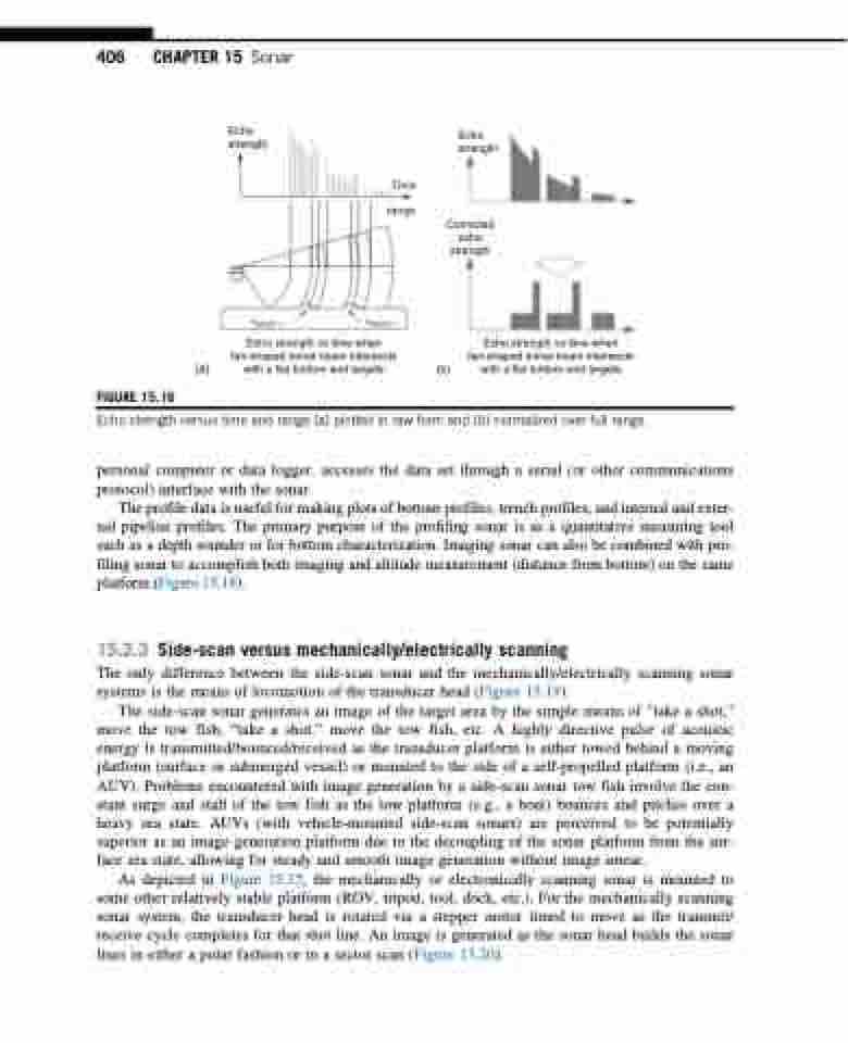
Echo strength
Echo strength
Corrected echo strength
Echo strength vs time when fan-shaped sonar beam intersects
(b) with a flat bottom and targets
Time range
FIGURE 15.16
(a)
Echo strength vs time when fan-shaped sonar beam intersects with a flat bottom and targets
TARGET 1 TARGET 1
Echo strength versus time and range (a) plotted in raw form and (b) normalized over full range.
personal computer or data logger, accesses the data set through a serial (or other communications protocol) interface with the sonar.
The profile data is useful for making plots of bottom profiles, trench profiles, and internal and exter- nal pipeline profiles. The primary purpose of the profiling sonar is as a quantitative measuring tool such as a depth sounder or for bottom characterization. Imaging sonar can also be combined with pro- filing sonar to accomplish both imaging and altitude measurement (distance from bottom) on the same platform (Figure 15.18).
15.2.3 Side-scan versus mechanically/electrically scanning
The only difference between the side-scan sonar and the mechanically/electrically scanning sonar systems is the means of locomotion of the transducer head (Figure 15.19).
The side-scan sonar generates an image of the target area by the simple means of “take a shot,” move the tow fish, “take a shot,” move the tow fish, etc. A highly directive pulse of acoustic energy is transmitted/bounced/received as the transducer platform is either towed behind a moving platform (surface or submerged vessel) or mounted to the side of a self-propelled platform (i.e., an AUV). Problems encountered with image generation by a side-scan sonar tow fish involve the con- stant surge and stall of the tow fish as the tow platform (e.g., a boat) bounces and pitches over a heavy sea state. AUVs (with vehicle-mounted side-scan sonars) are perceived to be potentially superior as an image generation platform due to the decoupling of the sonar platform from the sur- face sea state, allowing for steady and smooth image generation without image smear.
As depicted in Figure 15.15, the mechanically or electronically scanning sonar is mounted to some other relatively stable platform (ROV, tripod, tool, dock, etc.). For the mechanically scanning sonar system, the transducer head is rotated via a stepper motor timed to move as the transmit/ receive cycle completes for that shot line. An image is generated as the sonar head builds the sonar lines in either a polar fashion or in a sector scan (Figure 15.20).
