
Page 427 - The ROV Manual - A User Guide for Remotely Operated Vehicles 2nd edition
P. 427
420 CHAPTER 15 Sonar
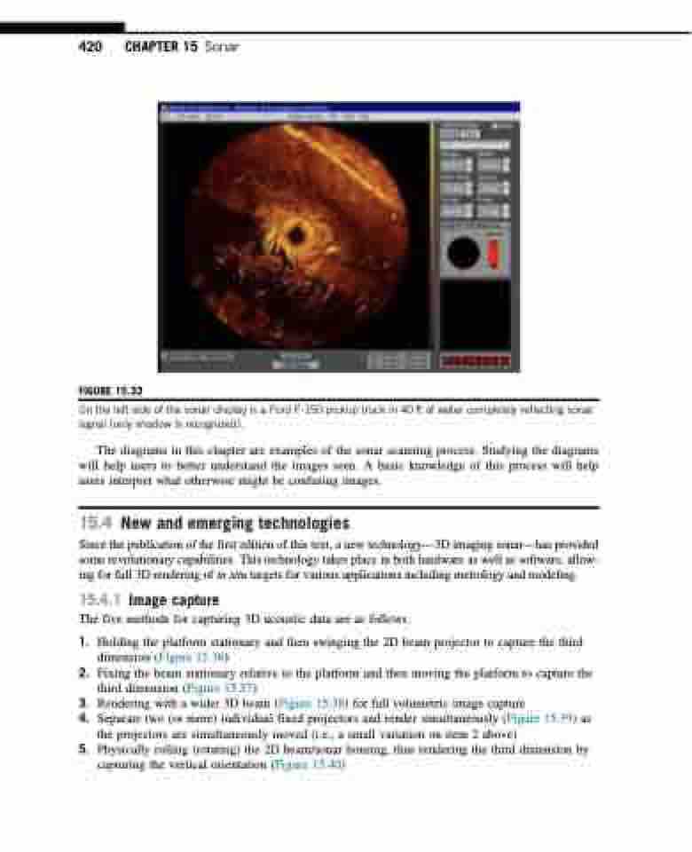
FIGURE 15.33
On the left side of the sonar display is a Ford F-150 pickup truck in 40 ft of water completely reflecting sonar signal (only shadow is recognized).
The diagrams in this chapter are examples of the sonar scanning process. Studying the diagrams will help users to better understand the images seen. A basic knowledge of this process will help users interpret what otherwise might be confusing images.
15.4 New and emerging technologies
Since the publication of the first edition of this text, a new technology—3D imaging sonar—has provided some revolutionary capabilities. This technology takes place in both hardware as well as software, allow- ing for full 3D rendering of in situ targets for various applications including metrology and modeling.
15.4.1 Image capture
The five methods for capturing 3D acoustic data are as follows:
1. Holding the platform stationary and then swinging the 2D beam projector to capture the third dimension (Figure 15.36)
2. Fixing the beam stationary relative to the platform and then moving the platform to capture the third dimension (Figure 15.37)
3. Rendering with a wider 3D beam (Figure 15.38) for full volumetric image capture
4. Separate two (or more) individual fixed projectors and render simultaneously (Figure 15.39) as
the projectors are simultaneously moved (i.e., a small variation on item 2 above)
5. Physically rolling (rotating) the 2D beam/sonar housing, thus rendering the third dimension by
capturing the vertical orientation (Figure 15.40)
