
Page 431 - The ROV Manual - A User Guide for Remotely Operated Vehicles 2nd edition
P. 431
424 CHAPTER 15 Sonar
Dual head multibeam
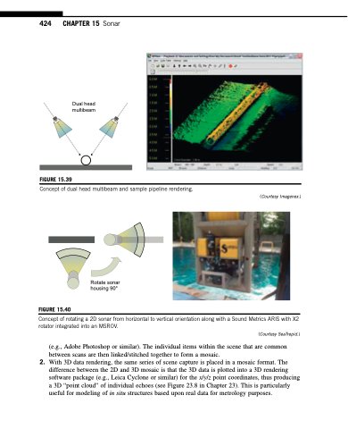
FIGURE 15.39
Concept of dual head multibeam and sample pipeline rendering.
Rotate sonar housing 90°
FIGURE 15.40
Concept of rotating a 2D sonar from horizontal to vertical orientation along with a Sound Metrics ARIS with X2 rotator integrated into an MSROV.
(Courtesy SeaTrepid.)
(e.g., Adobe Photoshop or similar). The individual items within the scene that are common
between scans are then linked/stitched together to form a mosaic.
2. With 3D data rendering, the same series of scene capture is placed in a mosaic format. The
difference between the 2D and 3D mosaic is that the 3D data is plotted into a 3D rendering software package (e.g., Leica Cyclone or similar) for the x/y/z point coordinates, thus producing a 3D “point cloud” of individual echoes (see Figure 23.8 in Chapter 23). This is particularly useful for modeling of in situ structures based upon real data for metrology purposes.
(Courtesy Imagenex.)
