
Page 465 - The ROV Manual - A User Guide for Remotely Operated Vehicles 2nd edition
P. 465
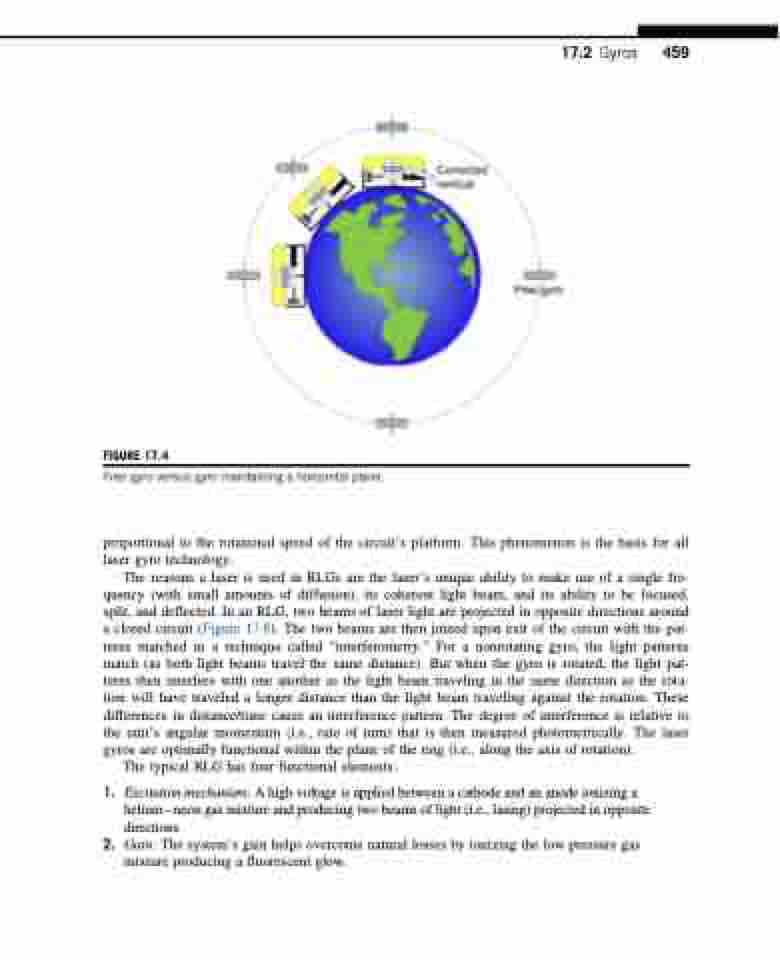
  FIGURE 17.4
Free gyro versus gyro maintaining a horizontal plane.
proportional to the rotational speed of the circuit’s platform. This phenomenon is the basis for all laser gyro technology.
The reasons a laser is used in RLGs are the laser’s unique ability to make use of a single fre- quency (with small amounts of diffusion), its coherent light beam, and its ability to be focused, split, and deflected. In an RLG, two beams of laser light are projected in opposite directions around a closed circuit (Figure 17.6). The two beams are then joined upon exit of the circuit with the pat- terns matched in a technique called “interferometry.” For a nonrotating gyro, the light patterns match (as both light beams travel the same distance). But when the gyro is rotated, the light pat- terns then interfere with one another as the light beam traveling in the same direction as the rota- tion will have traveled a longer distance than the light beam traveling against the rotation. These differences in distance/time cause an interference pattern. The degree of interference is relative to the unit’s angular momentum (i.e., rate of turn) that is then measured photometrically. The laser gyros are optimally functional within the plane of the ring (i.e., along the axis of rotation).
The typical RLG has four functional elements:
1. Excitationmechanism:Ahighvoltageisappliedbetweenacathodeandananodeionizinga heliumneon gas mixture and producing two beams of light (i.e., lasing) projected in opposite directions.
2. Gain: The system’s gain helps overcome natural losses by ionizing the low pressure gas mixture producing a fluorescent glow.
17.2 Gyros 459
