
Page 466 - The ROV Manual - A User Guide for Remotely Operated Vehicles 2nd edition
P. 466
460 CHAPTER 17 Navigational Sensors
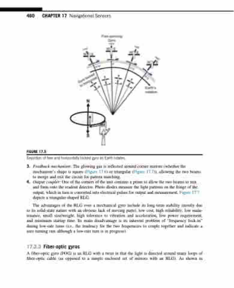
FIGURE 17.5
Depiction of free and horizontally locked gyro as Earth rotates.
3. Feedback mechanism: The glowing gas is reflected around corner mirrors (whether the mechanism’s shape is square (Figure 17.6) or triangular (Figure 17.7)), allowing the two beams to merge and exit the circuit for pattern matching.
4. Output coupler: One of the corners of the unit contains a prism to allow the two beams to mix and form onto the readout detector. Photo diodes measure the light patterns on the fringe of the output, which in turn is converted into electrical pulses for output and measurement. Figure 17.7 depicts a triangular-shaped RLG.
The advantages of the RLG over a mechanical gyro include its long-term stability (mostly due to its solid-state nature with an obvious lack of moving parts), low cost, high reliability, low main- tenance, small size/weight, high tolerance to vibration and acceleration, low power requirement, and minimum startup time. Its main disadvantage is its inherent problem of “frequency lock-in” during low-rate turns (i.e., the tendency for the two frequencies to couple together and indicate a zero turning rate although a low-rate turn is in progress).
17.2.3 Fiber-optic gyros
A fiber-optic gyro (FOG) is an RLG with a twist in that the light is directed around many loops of fiber-optic cable (as opposed to a simple enclosed set of mirrors with an RLG). As shown in
