
Page 488 - The ROV Manual - A User Guide for Remotely Operated Vehicles 2nd edition
P. 488
(a)
(b)
(c)
1500 μs
–15V
20A
18.2 Metal object detection 483
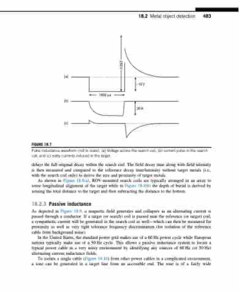
FIGURE 18.7
Pulse inductance waveform (not to scale). (a) Voltage across the search coil, (b) current pulse in the search coil, and (c) eddy currents induced in the target.
delays the full original decay within the search coil. The field decay time along with field intensity is then measured and compared to the reference decay time/intensity without target metals (i.e., with the search coil only) to derive the size and proximity of target metals.
As shown in Figure 18.8(a), ROV-mounted search coils are typically arranged in an array to sense longitudinal alignment of the target while in Figure 18.8(b) the depth of burial is derived by sensing the total distance to the target and then subtracting the distance to the bottom.
18.2.3 Passive inductance
As depicted in Figure 18.9, a magnetic field generates and collapses as an alternating current is passed through a conductor. If a target (or search) coil is passed near the reference (or target) coil, a sympathetic current will be generated in the search coil as well—which can then be measured for proximity as well as very tight tolerance frequency discrimination (for isolation of the reference cable from background noise).
In the United States, the standard power grid makes use of a 60 Hz power cycle while European nations typically make use of a 50 Hz cycle. This allows a passive inductance system to locate a typical power cable in a very noisy environment by identifying any sources of 60 Hz (or 50 Hz) alternating current inductance fields.
To isolate a single cable (Figure 18.10) from other power cables in a complicated environment, a tone can be generated in a target line from an accessible end. The tone is of a fairly wide
250 V
