
Page 558 - The ROV Manual - A User Guide for Remotely Operated Vehicles 2nd edition
P. 558
20.2 Remotely operated (ROV-positioned) tooling and sensors 555
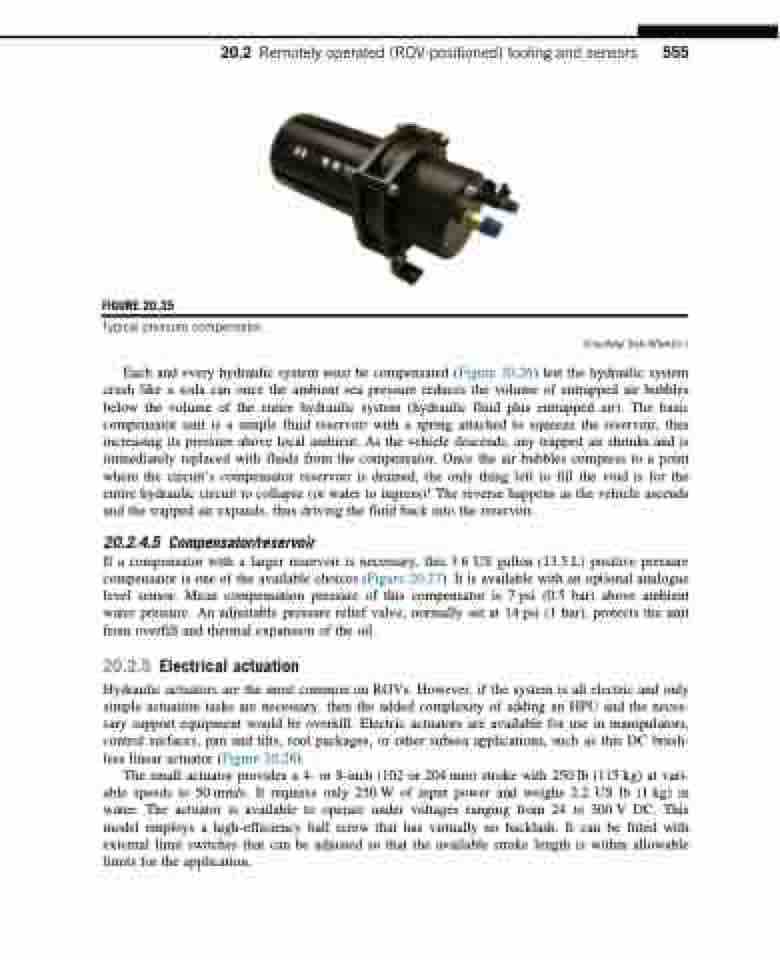
FIGURE 20.25
Typical pressure compensator.
Each and every hydraulic system must be compensated (Figure 20.26) lest the hydraulic system crush like a soda can once the ambient sea pressure reduces the volume of entrapped air bubbles below the volume of the entire hydraulic system (hydraulic fluid plus entrapped air). The basic compensator unit is a simple fluid reservoir with a spring attached to squeeze the reservoir, thus increasing its pressure above local ambient. As the vehicle descends, any trapped air shrinks and is immediately replaced with fluids from the compensator. Once the air bubbles compress to a point where the circuit’s compensator reservoir is drained, the only thing left to fill the void is for the entire hydraulic circuit to collapse (or water to ingress)! The reverse happens as the vehicle ascends and the trapped air expands, thus driving the fluid back into the reservoir.
20.2.4.5 Compensator/reservoir
If a compensator with a larger reservoir is necessary, this 3.6 US gallon (13.5 L) positive pressure compensator is one of the available choices (Figure 20.27). It is available with an optional analogue level sensor. Mean compensation pressure of this compensator is 7 psi (0.5 bar) above ambient water pressure. An adjustable pressure relief valve, normally set at 14 psi (1 bar), protects the unit from overfill and thermal expansion of the oil.
20.2.5 Electrical actuation
Hydraulic actuators are the most common on ROVs. However, if the system is all electric and only simple actuation tasks are necessary, then the added complexity of adding an HPU and the neces- sary support equipment would be overkill. Electric actuators are available for use in manipulators, control surfaces, pan and tilts, tool packages, or other subsea applications, such as this DC brush- less linear actuator (Figure 20.28).
The small actuator provides a 4- or 8-inch (102 or 204 mm) stroke with 250 lb (115 kg) at vari- able speeds to 50 mm/s. It requires only 250 W of input power and weighs 2.2 US lb (1 kg) in water. The actuator is available to operate under voltages ranging from 24 to 300 V DC. This model employs a high-efficiency ball screw that has virtually no backlash. It can be fitted with external limit switches that can be adjusted so that the available stroke length is within allowable limits for the application.
(Courtesy Sub-Atlantic.)
