
Page 228 - Maxwell House
P. 228
208 ANTENNA BASICS
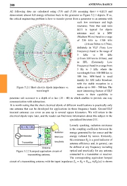
All following data are calculated using (5.9) and (5.10) assuming that = 4 ∆ and
⁄
demonstrate almost full energy reflection back to the generator as Figure 5.2.1 depicts. If so,
the critical engineering problem is how to transfer power from a generator to an antenna with
such low resistance and high
reactance. Note that said ratio
∆ is typical for dipole
⁄
antennas used in a MW
(Medium Wave) band in a range
of 530 kHz to 1700 kHz
( from 566m to 176m),
definitely in VLF (Very Low
Frequency) band in the range of
= 0.001 3 kHz to 30 kHz
( from 100 km to 10 km), and
= 0.1 in EFL (Extremely Low
Frequency) band in a range from
3 Hz to 3 kHz where the
wavelength from 100 000 km to
100 km. MW-band is used
mainly for AM radio broadcast
with the stable reception in a
Figure 5.2.1 Short electric dipole impedance vs. radius up to 300 – 500 km. The
wavelength most interesting feature of ELF
waves is their capability to
penetrate salt seawater to a depth of at last (10 – 40) m which enables to provide one-way
communication with submarines.
It is worth noting that the short electrical dipole of different modifications is practically only
one antenna that can be developed for applications in those frequency bands. Ground ELF
transmit antennas can cover an area up to several square kilometers. We will return to the
electrical dipole topic later, and the reader can find more information about this subject in the
specialized literature [33].
Loosely speaking, radiation resistance
is the coupling coefficient between the
energy generated by the source and the
energy radiated by waves. Evidently,
this resistance is a good indicator of
Σ
antenna efficiency and, in general, can
be defined at any frequency including
Figure 5.2.2 Lumped equivalent circuit of optical and practically for any antenna
transmitting antenna connected to a transmitter or receiver.
The corresponding equivalent lumped
circuit of a transmitting antenna with the input impedance = + +j () is shown
Σ
Σ