
Page 287 - House of Maxell
P. 287
Chapter 5 267
customer, base stations, etc. Such antennas customary called smart antennas become an integral
part of wireless radio and mobile communications systems.
Unluckily for us, the conformal antenna electromagnetic analysis is based on sophisticated
mathematical analysis and numerical algorithms that are beyond the scope of this book. So we
refer the reader to the specialized literature [9].
5.6.3 Effect of Beam Focusing
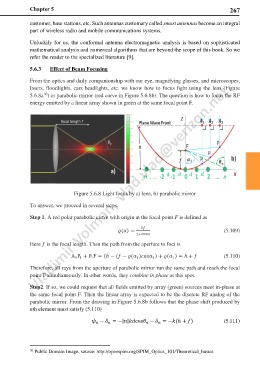
From the optics and daily companionship with our eye, magnifying glasses, and microscopes,
lasers, floodlights, cars headlights, etc. we know how to focus light using the lens (Figure
30
5.6.8a ) or parabolic mirror (red curve in Figure 5.6.8b). The question is how to focus the RF
energy emitted by a linear array shown in green at the same focal point F.
Figure 5.6.8 Light focus by a) lens, b) parabolic mirror
To answer, we proceed in several steps.
Step 1. A red polar parabolic curve with origin at the focal point F is defined as
2
(α) = (5.109)
1+cosα
Here is the focal length. Then the path from the aperture to foci is
A P + P F = (ℎ − ( − (α )α ) + (α ) = ℎ + (5.110)
1 1
1
1
1
1
Therefore, all rays from the aperture of parabolic mirror run the same path and reach the focal
point F simultaneously. In other words, they combine in phase at this spot.
Step2. If so, we could request that all fields emitted by array (green) sources meet in-phase at
the same focal point F. Then the linear array is expected to be the discrete RF analog of the
parabolic mirror. From the drawing in Figure 5.6.8b follows that the phase shift produced by
nth element must satisfy (5.110)
− = −||cos − = −(ℎ + ) (5.111)
30 Public Domain Image, source: http://openspim.org/SPIM_Optics_101/Theoretical_basics