
Page 365 - House of Maxell
P. 365
FEED LINE BASICS 345
differential phase shifter switches [19] used as RF power commutator at very high peak (from
tens to hundreds of kilowatts) and average power levels (from hundreds to thousands of watts).
6.8.5 Resonance Isolators
Note that a nonreciprocal phase shifter can be transformed into two-port unidirectional device
called a resonance isolator by establishing the bias intensity such as the wave with CP ()
+
reaches the ferromagnetic resonance and dissipates in ferrite. As soon as the wave changes the
direction of its propagation to opposite, i.e. → −, the wave CP switches to () and
−
propagates almost without loss. In general, isolators are built-in between the sensitive to
mismatch generator (mostly solid-state) and the load that reflects the sizable portion of RF
power back to generator hurting its performance thereby reducing its output power, initiating
electrical or thermal breakdown, etc. Evidently, the forward wave coming from the generator
should be () relative to positive bias direction. Then the backward wave polarized as ()
+
−
is almost entirely lost being absorbed inside ferrite. The latter is a serious disadvantage of
resonance isolator because the ferrite is heated twice, i.e. by forward wave first slightly and
then by absorbed backward wave energy. The excessive temperature increase in ferrite stub
might lead to quite severe degradation by
destroying it, shifting the resonance
frequency, increasing forward wave loss,
etc. The isolators based on circulating and
displacement effect (see below) perform
much better. Consequently, they are used
more frequently.
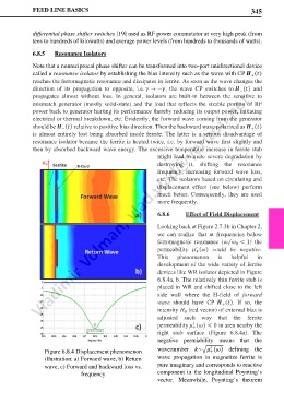
6.8.6 Effect of Field Displacement
Looking back at Figure 2.7.3b in Chapter 2,
we can realize that at frequencies below
ferromagnetic resonance ( < 1) the
⁄
0
permeability () could be negative.
′
+
This phenomenon is helpful in
development of the wide variety of ferrite
devices like WR isolator depicted in Figure
6.8.4a, b. The relatively thin ferrite stub is
placed in WR and shifted close to the left
side wall where the H-field of forward
wave should have CP (). If so, the
+
intensity (red vector) of external bias is
0
adjusted such way that the ferrite
permeability () < 0 in area nearby the
′
+
right stub surface (Figure 6.8.4a). The
negative permiability means that the
′
Figure 6.8.4 Displacement phenomenon wavenumber ~� () defining the
+
illustration: a) Forward wave, b) Return wave propagation in magnetize ferrite is
wave, c) Forward and backward loss vs. pure imaginary and corresponds to reactive
frequency component in the longitudinal Poynting’s
vector. Meanwhile, Poynting’s theorem