
Page 422 - House of Maxell
P. 422
402 Chapter 8
in GHz are depicted in Figure 8.2.10a that confirms this statement. The isolation nearby
the central frequency is quite good exceeding 20 B. The equal power division takes place
at frequency 2.8687 GHz and nearby and equals to 3.35dB (triangle marker) but not
expected 3dB.
Such result can be explained to some extent by the mismatch, level of energy coming to the
isolated port3, and not the perfect accuracy of the numerical simulation. Note that the microstrip
in CST model was assumed lossless. Nevertheless, the mysterious too high lack of 2.5% in the
balance of power demonstrated by Figure 8.2.10c must be explained. Peace in mind will come
if we remember that a microstrip is a line of open type and might radiate rather intensively as
soon as the discontinuities are presented. Figure 8.2.10b shows the normalized in the dB
radiation pattern of hybrid that covers the upper hemisphere almost uniformly and takes about
1% of input power. It might be the source of undesired interference.
The hybrid operating bandwidth can be significantly improved by connecting the main and
secondary line with multiple branches (up to octave for a three-branch hybrid). Nevertheless,
one or several hybrids’ characteristics such as its size, cost, interference, and bandwidth are
often the biggest limitations in their implementation. Note that there are many different variants
of branch hybrids. In particular, one of the most attractive design is a hybrid where all line
sections or some of them are replaced with lumped components. If so, substantial size reduction
can be achieved at the lower microwave frequencies. Besides, such approach might provide low
insertion loss, wider bandwidth, and high level of miniaturization, making it a good fit for a
monolithic microwave integrated circuit. Unfortunately, this topic goes far beyond our course
devoted mainly to electrodynamics. We refer the reader to the specialized literature [2] for more
details.
8.2.8 Microstrip Ring Hybrid
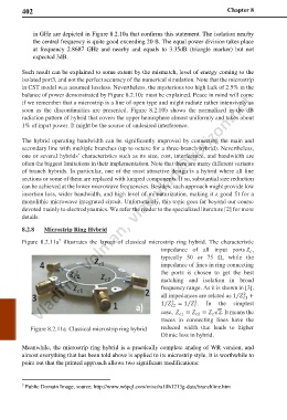
Figure 8.2.11a illustrates the layout of classical microstrip ring hybrid. The characteristic
7
impedance of all input ports ,
typically 50 or 75 Ω, while the
4 impedance of lines in ring connecting
the ports is chosen to get the best
matching and isolation in broad
frequency range. As it is shown in [3],
3 2 all impedances are related as 1 +
2
⁄
1
1 a) 1 2 = 1 . In the simplest
2
2
⁄
⁄
case, = = √2. It means the
1 2
traces in connecting lines have the
Figure 8.2.11a Classical microstrip ring hybrid reduced width that leads to higher
Ohmic loss in hybrid.
Meanwhile, the microstrip ring hybrid is a practically complete analog of WR version, and
almost everything that has been told above is applied to its microstrip style. It is worthwhile to
point out that the printed approach allows two significant modifications:
7 Public Domain Image, source: http://www.w6pql.com/misc/ra18h1213g-data/branchline.htm